|
|


 Arabic
 Bengali
 Chinese
 English
 French
 German
 Hebrew
 Hindi
Hindi Italian
 Japanese
 Korean
 Malay
Malay Polish
 Portuguese
 Spanish
 Turkish
 Ukrainian
 Vietnamese
|
ENCYCLOPEDIA OF RADIO ELECTRONICS AND ELECTRICAL ENGINEERING
Simple hidden wiring finder without power supply. Encyclopedia of radio electronics and electrical engineering
Encyclopedia of radio electronics and electrical engineering / Electrician's Handbook Sometimes in everyday life it becomes necessary to determine the location of electrical wiring in the walls or ceilings of buildings. The journal "Radio" published many articles describing such devices, both stand-alone [1-6] and in the form of prefixes to the multimeter [7, 8]. However, they all require a power source or are powered by a multimeter, which, however, also has its own source. Is it possible to make a seeker that does not require a power source? It is clear that such a device should at least have an indicator. It is also intuitively clear that this indicator should be micro-powerful and preferably optical. From the whole variety, you can choose gas discharge lamps (neon), LEDs and LCDs. In neon lamps, the current is tenths of a milliamp, but the ignition voltage is very high - tens of volts. Among the LEDs, you can find devices with a current of tenths of a milliamp and a voltage of 1,5 ... 2 V. However, according to the author, the most economical are LCDs. They consume current from units to tens (sometimes hundreds) of microamperes at a voltage of one volt. In addition, unlike LEDs, they do not need a constant voltage, which means that there is no need for a rectifier. So, the indicator is selected. What's next? How to make it indicate the presence of an alternating electric field, given that the seeker should not have a galvanic connection with the wiring? Recall that usually electrical wiring is made with a cable with two or three insulated wires with a diameter of 1 ... 2 mm in common insulation. One of the wires is zero or neutral, the second is phase with an effective (rms, effective) voltage of 230 V relative to zero, the third is grounding (it is not in a two-wire cable). Sometimes, extremely rarely, there are situations when the voltage in the network is formed by two phase wires. In any case, we can assume that at some distance from the wires, exceeding their diameter and the distance between them, an alternating electric field is created by two wires with a voltage of 230 V between them.
Considering that the LCD, as an element of the electrical circuit, is similar to a capacitor [9], consider the circuit in Fig. 1. On it SZhKI - the capacity of the LCD (one element relative to the total output); 1 and 2 - network wires; 3 and 4 - points to which LCD outputs are connected; C1-C4 - capacitors formed by network wires and connection points of LCD outputs. Taking into account the fact that, in the first approximation, at a great distance, exceeding the distance between the network wires, the capacitance of capacitors C1-C4 can be considered the same, we get C=CLCD (ULCD/(Uc - ORLCD)), where C is the capacitance of capacitors C1 -C4; ULCD - LCD voltage; Uc - mains voltage. A single-digit seven-element LCD FP-056P was chosen as an indicator. Measurements showed that the capacitance of its element g relative to the common output is slightly less than 80 pF, and the "ignition" voltage of the element does not exceed 3 V. Substituting these values into the formula, we find that the capacitance of capacitors C1-C4 must be at least 1 pF. Such a capacitance can be provided, for example, by a piece of cable with two cores with a diameter of 1 mm in common insulation, approximately 150 ... 200 mm long, at a distance of 20 mm from the mains wires. However, it should be taken into account that such a cable has its own linear capacitance, which should be added to the capacitance of the LCD, since they are connected in parallel. For example, the measured linear capacitance of a cable with two cores with a diameter of 1 mm, a distance between them of 2 mm and in PVC insulation is about 70 pF / m. This means that a piece of such a wire 150 mm long has a capacitance of about 10 ... 15 pF. The conducted experiments showed that in real situations, to search for hidden wiring, the length of the searcher wires must be at least 350 ... 400 mm. It is extremely inconvenient to work with such a finder, in addition, the electrical wiring must have straight sections of such a length, which is far from always done in practice. It is possible, of course, to separate the wires from each other at a greater distance, thereby reducing their own capacitance, but as experiments show, without reducing the sensitivity, the length of the wires cannot be significantly reduced. Is it possible to replace the wires with something else? From the course of the theoretical foundations of electrical engineering, it is known that the capacitance of a wire over an infinite conducting plane is twice that of two wires spaced at the same distance. It can be assumed that the capacitance of a wire located above a plate of finite width will have some intermediate value between these extreme cases. Therefore, the wires can be replaced by plates, which should provide the necessary capacitance. The problem of calculating the capacitance between two plates of the same width lying in the same plane was solved in [10]. There is also a graph of the dependence of the linear capacity on the ratio of the distance between the plates to the width of the plate (Fig. 9.4 on p. 227). Please note that to get linear capacity in picofarads per meter, you need to multiply the capacitance value from this graph by 8,86. Preliminary calculations showed that to indicate the presence of an alternating electric field at a distance of about 20 mm from the wires, plates with a width of 15 ... cable) with a gap of 20...2 mm between them and a length of 3...200 mm. An increase in the length of the plates also leads to an increase in the sensitivity of the device.
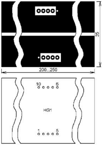
Based on this, it was decided to assemble the seeker on a printed circuit board. Its drawing is shown in Fig. 2, it is made of fiberglass with a thickness of 1,5 mm foiled on one side. In the middle of the board, parallel to the wide sides, the foil is removed to a width of 2 mm. The resulting two areas are points 3 and 4 in Fig. 1. Measurements showed that the capacitance between two pads 205 mm long and 16,5 mm wide is about 6 pF, respectively, the linear capacitance is about 30 pF / m, which is more than half the linear capacitance of two wires in common insulation, which was speech above. A common output of the LCD is soldered to one site on the board, and the output of the g element is soldered to the other. This is done in order for the g element to indicate the direction of the electrical wires. Such a finder confidently "recognizes" the presence of electrical wiring at a distance of 15 ... 20 mm, which is quite enough for practice. If one “lit” element is not enough for someone, you can connect two located at the edges - elements a and d (pins 7 and 2 of the FP-056P LCD), leaving the common pin unconnected. In this case, the "ignition" voltage will double, but the total capacitance of the LCD will decrease by half, since its elements will be connected in series. Experiments with such inclusion of two elements showed that the sensitivity of the seeker did not change noticeably, but an "unpleasant" effect appeared associated with the chaotic and unpredictable inclusion of unconnected elements, although it can be considered positive, since there is an additional indication of the presence of an alternating electric field. It is very simple to use the finder: you need to attach the board to the wall and move it, turning it at small angles in opposite directions. According to the maximum "glow" of the element or elements, the location of the "occurrence" of the electrical wiring is determined (Fig. 3).
You can increase the sensitivity (increase the distance at which the finder "feels" the wiring) by touching one of the board pads with your finger. In this case, one of the terminals of the LCD is connected to the ground through the human capacitance. Since in most cases the neutral wire of the electrical wiring is also connected to ground, theoretically the capacitance of capacitors C1 and C3 (or C2 and C4, depending on which LCD terminal is touched) for normal operation of the finder may be less. True, this is possible only if the capacity of a person is greater than the capacity of C1 and C3 (or C2 and C4), which is far from always true. First of all, it depends on the environment, on the location of a person relative to grounded structures, mainly heating pipes and plumbing or reinforcement of reinforced concrete structures, as well as on the location of the electrical wiring itself. In any case, it's worth a try! Literature
Author: I. Podushkin
Traffic noise delays the growth of chicks
06.05.2024 Wireless speaker Samsung Music Frame HW-LS60D
06.05.2024 A New Way to Control and Manipulate Optical Signals
05.05.2024
▪ The moth's eye will help create an anti-reflective coating ▪ Sony a42 II full frame 99MP camera ▪ Space amethyst in a dying star ▪ Alternative energy has fallen sharply
▪ section of the site Household electrical appliances. Selection of articles ▪ article The state of the biosphere and human health. Basics of safe life ▪ article What is the difference between a broker, a dealer, a broker? Detailed answer ▪ article Linear pipeline. Standard instruction on labor protection ▪ article Metronome-conductor. Encyclopedia of radio electronics and electrical engineering ▪ article Three cards (Find a lady). Focus Secret
Home page | Library | Articles | Website map | Site Reviews
www.diagram.com.ua |


 Leave your comment on this article: