|
|


 Arabic
 Bengali
 Chinese
 English
 French
 German
 Hebrew
 Hindi
Hindi Italian
 Japanese
 Korean
 Malay
Malay Polish
 Portuguese
 Spanish
 Turkish
 Ukrainian
 Vietnamese
|
ENCYCLOPEDIA OF RADIO ELECTRONICS AND ELECTRICAL ENGINEERING
Electrician's toolkit. Encyclopedia of radio electronics and electrical engineering
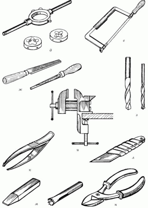
Encyclopedia of radio electronics and electrical engineering / electrician's tool It is necessary to start any business with the formation of a set of tools, fixtures and appliances that may be required in the production of work. Electrical work is no exception: laying wiring, identifying the causes of malfunctions, repairing electrical appliances. For electrical work, a set of standard tools and a few simple devices (homemade and industrial design) are required. These are general-purpose hand tools (Fig. 1): a set of wrenches, a set of screwdrivers, pliers, taps and dies of relatively small sizes (from M2 to M6), a tap wrench and a die holder, metal drills from 1 to 10 mm (among them there should also be drills with hard-alloy - victorious - soldering), a hacksaw for metal, files, a small vice, tweezers, a chisel and a jumper, a hammer, a mounting knife, scissors, side cutters (side cutters).
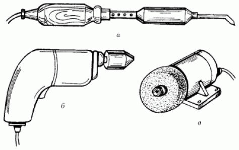
To punch grooves and sockets for wires, switches and sockets in the walls, in addition to a chisel, jumper and drills, you will need a hammer. This is followed by power tools (Fig. 2): an electric soldering iron with a set of consumables (solder, flux), an electric drill, an electric grinder.
These tools are needed for a wide variety of jobs: from preparing holes in the walls for fixing hidden wiring to sharpening tools. Even for electrical work, devices are needed with which it is convenient to determine the parameters of the electrical circuit and the presence of voltage in the network. First of all, these are indicators and probes (Fig. 3).
The simplest circuit voltage indicator can be made independently from a threaded cartridge with a low-power incandescent lamp, two pieces of insulated wire and two metal probes. However, using this device, you can only determine the presence or absence of voltage in the network, but it is impossible to determine which of the wires is phase and which is neutral. This is easy to find out with the help of industrial indicators, the most common of which is an indicator screwdriver. To determine the presence of voltage in the electrical network, on the current-carrying parts of devices and devices, to find the phase wire on the contacts, the tip of the screwdriver is attached to the test area; the indicator is activated by touching its contact head with a hand (the current flowing through the human body at a mains voltage of 220 V is a fraction of a milliamp and does not pose any danger to it). The indicator lamp lights up if the screwdriver touches a live wire or contact under voltage; when you touch the neutral wire or contact, the light does not light up. But when it is necessary not only to determine the presence or absence of current in the network, not only to designate “phase” or “zero”, but also to measure certain current parameters, then this can be done using special devices: ammeter, voltmeter or ohmmeter. In fairness, it should be said that not even all professional electricians have all these devices available. It is much more rational and easier to get a combined ammeter, popularly called a tester; With it, you can measure the strength and voltage of DC, the average value of current and AC voltage, DC resistance. Range of measured parameters: current - in the range from 0 to 2,5 A; voltage - up to 1000 V; DC resistance up to 10000 kOhm. The device is equipped with sufficiently powerful protection: it is able to withstand short-term overloads up to 25 times the values of the final value of the measuring range. The big problem is determining the location of the break in the hidden wiring. For a person who is not initiated into the subtleties of electrical engineering, the only tools with which this can be done are a hammer and a chisel. But you can find the place of the cliff without making such a huge investment of time, labor and money (for the subsequent plastering of the walls), using a fairly simple device, the schematic diagram of which is shown in Fig. 4.
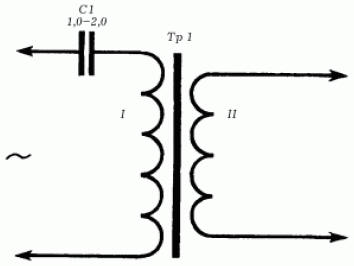
The operation of the device is based on the registration of an electric field that is formed around a conductor (wire) under voltage. The power of the device allows you to register a current with a frequency of 50 Hz at a distance of 6-8 cm from the conductor. Such a device can be purchased ready-made or try to assemble it according to the following description. To assemble the device and detect a malfunction in hidden wiring, the following components are required: a four-stage audio frequency amplifier with a gain of 3000-5000 units, a rectifier, a key stage, an audio frequency generator at 900-1600 Hz, two 3336L batteries, a transformer, an antenna and headphones ( headphones). To power the device, 3336L batteries are connected in series (their total current is 5-8 mA). The conductor with current in antenna A induces a voltage of 50 Hz in the device, which is increased by an audio frequency amplifier (assembled on transistors T1-T4). Next, the voltage is rectified by diode D1 (its output value is 0,2-0,4 V) and goes to the base of transistor T5 of the key stage. Under the influence of voltage, the blocking oscillator, assembled on the transistor T6, begins to generate audio frequency oscillations, which are clearly audible in the headphones connected to the generator. All parts of the device, except for the VK1 switch, batteries, G1 sockets and telephones, are placed on a getinax board 12 x 7,2 cm in size. The board itself, together with batteries, sockets and the switch toggle switch, is placed inside a metal case 15 x 7,8 x 4,5 .13 mm. Antenna A measuring 6,5 x XNUMX cm, made of sheet copper foil, is mounted in the window of the housing cover on an insulating getinax board. For normal operation of the device, the static current gain (Vst) of all transistors of the device must be in the range of 35-50. The transformer Tr1, mounted in the device, is made on a magnetic circuit Ш5 x 6. The primary winding of the transformer (I) should consist of 1500 turns of PEV wire with a diameter of 0,1 mm, the secondary winding (II) should consist of 600 turns of the same wire. After installing the transformer, you should check the operability of the blocking generator, for which the collector and emitter of the transistor T5 are temporarily short-circuited with a wire jumper: with the correct connection of the terminals of the winding (I) of the transformer Tr1, the generator starts to work, otherwise the terminals must be swapped. The key stage is put into operation by applying a negative voltage of 5-0,2 W to the base of the transistor T0,4, which is removed from the divider. The divider is made up of fixed resistors with a resistance of 5,1 kOhm and 150 Ohm, included in the common power circuit (if you use a variable resistance as resistor R2 in the circuit, the device will be more sensitive). The supply voltage of the blocking generator during the adjustment of the key stage should be 7-8 V. The adjustment of the audio frequency amplifier itself is carried out by selecting the resistance of the resistor R3, on which the operating modes of the transistors T2-T4 depend. After assembling and adjusting all the components and the device itself as a whole, you can begin to determine the location of damage to hidden wiring (passing along its route). Voltage is applied to the circuit, route, the fault location of which is to be determined; connect headphones to the device and turn on its power. An audible signal, heard in the phones for some time after switching on and corresponding to the tone of the generator, indicates that the device is working normally. Next, the antenna of the device is directed towards the intended route of hidden electrical wiring: depending on the distance between the wire passing through the wall and the antenna, the tone of the generator will increase or decrease, which will make it possible to trace the route of the wire in the wall. The disappearance of the sound signal in the head phones indicates the location of the wire break (as a rule, the tone of the generator disappears at a distance of 5-7 cm from the break point). Throughout the entire time of the examination of the electrical wiring by the device, its body must be in constant contact with the hands. If the device for determining the route and the place of a break in hidden wiring is somewhat improved, then with its help it will be possible to determine the place of a short circuit (of the same hidden wiring). To do this, an electromagnetic sensor is connected to the input of the device through the T1 connector, which makes it possible to register the magnetic field of conductors with alternating current. It is an open magnetic circuit made of W-shaped transformer iron with a coil of 3000-6000 turns of PEV-2 wire with a diameter of 0,1-0,12 mm; sensor core Ш12 (Ш9, Ш10, Ш14, etc.); set thickness - 12-15 mm. To connect the sensor to the device, a flexible shielded cable 1,5–2 m long is used, and the sensor itself is mounted on a tripod. The transformer Tr1 of a modified improved device is wound on the Sh16 magnetic circuit with a package 32 mm thick. Its primary winding (I) in this case should contain 1560 turns of PEV-2 wire with a diameter of 0,14 mm, and the secondary winding (II) - 8 turns of PEV-2 wire with a diameter of 0,8 mm. In addition, capacitor C1 is included in the primary winding circuit; it is necessary in order to limit the current in the secondary circuit when searching for a short circuit in short sections (5-8 m). The technique for determining the location of a short circuit is as follows: - the wiring section, the short circuit on which is to be determined, is connected to a step-down transformer (Fig. 5);
- at the moment when the open side of the magnetic circuit approaches the short circuit point, an audible signal appears in the headphones. Beyond the short circuit, there is no magnetic field in the wires and therefore the signal disappears. If for some reason it is not possible to assemble the device described above, we offer a diagram of another device for determining the hidden wiring route in a non-contact way - a voltage detector. It is based on the principle of reaction to the electrical component of the electromagnetic field. Moreover, the voltage detector allows you to determine the wiring route even if it is de-energized. The structure of the voltage signaling device (Fig. 6): an antenna - an electrometric amplifier - a discriminator and pulse expansion unit - an audible alarm unit - a unit for monitoring the health of the device.
The voltage signaling device is powered by a 9 V battery; current consumption in the indication mode - 15 mA, in the absence of a signal - 5 mA. Weight of the device - 250 g; dimensions - 10 x 5 x 3 mm. The electrometric amplifier is based on the MS2 integrated circuit - a voltage follower with a field-effect transistor at the input. Its sensitivity depends on the resistance R6, if necessary, it can be adjusted within a small range by the resistor R5 (if the sensitivity is insufficient, the resistance of the resistor R5 is reduced, if it is too large, it is increased). A rectifier on diodes D1 and D2 and a single-viator on transistors T1 and T2, the threshold of which is set by diode D3, form a discriminator and pulse extension unit. The sound signaling unit is mounted according to the multivibrator circuit on transistors T3 and T4. The collector circuit of the transistor T4 includes an electromagnetic capsule Gr1 type DEMSh or TM-2A. The asymmetric multivibrator circuit on the MC1 integrated circuit underlies the health monitoring unit. The multivibrator generates short pulses, the repetition frequency of which determines the capacitance of the capacitor C1. When pulses through the capacitor C2 arrive at the An1 antenna with a frequency of about 0,2 Hz, the device is triggered and the signaling device gives a single sound signal with a duration of less than 0,1 s; the signal is evidence of the correctness of the voltage signaling device. If the voltage detector is introduced into the electric field, an electromotive force (EMF) will be induced in the antenna, which will go to the input of the amplifier. Next, the variable component of the current through the capacitor C3 will be fed to the discriminator. In order for the single vibrator to start and the sound signaling unit to start generating a sound signal, the current in the signaling device must reach a predetermined level (the current depends on the distance between the antenna and the current-carrying parts of the electrical installation: the shorter the distance, the greater the current strength). As a basis for mounting a voltage detector, a printed circuit board is used, which, together with the battery, is placed in a metal case; end walls of the housing must be made of insulating material. One of these walls acts as an antenna, so it is made of foil-coated getinaks (the foil is removed from part of the getinaks surface). The dimensions of the antenna are corrected when setting up the device. The button for turning on the signaling device and the socket of the Sh1 connector for connecting the charger are mounted in the second end wall. The chamber of the acoustic resonator is connected to the electromagnetic capsule Gr1. Adjustment of the voltage signaling device consists in adjusting the response threshold according to the electric field strength: - first of all, they check the current consumed in the absence of an audible signal, it should not be more than 6 mA; - then the collector and emitter of the transistor T2 are short-circuited, and an audible signal should appear; in the absence of a signal, check the multivibrator on the MC1 chip; - then the signaling device is gradually brought closer to the distance allowed by safety regulations to the current-carrying wire; an audible signal indicates the operation of the device. A properly adjusted signaling device allows you to register an alternating voltage of 220/380 V at a distance of 5-10 cm. As with the previously described device, the metal case of the signaling device must be in constant contact with the hand. Screwdrivers-indicators with a liquid crystal display are on sale. Such a screwdriver will help determine the presence of an alternating voltage of 36-220 V (sometimes even through the wire insulation). Author: Korshevr N.G.
Traffic noise delays the growth of chicks
06.05.2024 Wireless speaker Samsung Music Frame HW-LS60D
06.05.2024 A New Way to Control and Manipulate Optical Signals
05.05.2024
▪ Alternate Reality for Scouts ▪ Intel to move to tri-gate transistors in 2010 ▪ Xiaomi Mi PTZ Camera for hoverboard ▪ Rocket for flights to Mars and flights on Earth
▪ site section Power supplies. Article selection ▪ article Not in the tooth with a foot. Popular expression ▪ article Where do they pay and greet with rain? Detailed answer ▪ article Safety requirements for extracurricular and extracurricular activities ▪ article OZ angle corrector. Encyclopedia of radio electronics and electrical engineering
Home page | Library | Articles | Website map | Site Reviews
www.diagram.com.ua |


 Leave your comment on this article: