|
|


 Arabic
 Bengali
 Chinese
 English
 French
 German
 Hebrew
 Hindi
Hindi Italian
 Japanese
 Korean
 Malay
Malay Polish
 Portuguese
 Spanish
 Turkish
 Ukrainian
 Vietnamese
|
ENCYCLOPEDIA OF RADIO ELECTRONICS AND ELECTRICAL ENGINEERING Finalization of the AC-35 (S-90) acoustic system. Encyclopedia of radio electronics and electrical engineering
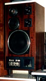
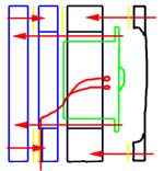
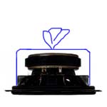
Encyclopedia of radio electronics and electrical engineering / Speakers Acoustic systems AC-35 (S-90) are known as one of the best acoustic systems of pre-perestroika times. They were produced by different factories and in a slightly different configuration, without changing in essence. For the modification, systems 35AS-012 GOST 23262-88 of the Bryansk Electromechanical Plant, released in January 1990, were used. They contain speakers 75GDN-3-4, 20GDS-3-4, 10GDV-2-16 and are designed for a frequency range of 40-25000 Hz (resistance 4 ohms). The refinement made it possible to reduce the unevenness of the frequency response at medium frequencies and get rid of their characteristic “clicking” and sharpness at high frequencies by replacing the high-frequency head and mid-frequency damping. For the conversion we used Peerless 100 DT 26 72 SF FF WA 8 tweeters (catalog number 811827). Quite a good option, especially if you are not embarrassed by the prospect of spending about $53 on them, which is comparable to the cost of the S-90s themselves. So, in the process of work, the following changes were made: Installing speakers on spikes As a result of these changes, the sound of the speakers has changed for the better. Gone are the "tsikka", whistling and whispering at high frequencies. The sound stage has expanded, acquiring greater depth and transparency. Low frequencies sounded more elastic and clear. The sound of the speakers has become more natural and natural. For replacement, a Peerless 811827 head with a magnetic fluid in the gap was chosen. Maximum power 130 W, impedance 8 ohms, resonant frequency 1130 Hz and sensitivity 92 dB. The external dimensions of this head are somewhat smaller than the standard one, and the impedance is two times lower. This led to the need to manufacture an isolated box for it and change the values of the elements in the crossover circuit. The box was made of two squares (11x11cm) of 10mm plywood. A hole was cut out in one of the squares, with a diameter of 90 mm, and a small selection was made at the end, for signal wiring. In the second square, 4 holes are made for the head mounting screws or attachment points for screws are outlined. The squares, after laying the wire, are fastened with 4 small screws with a coating of the joint surface with plasticine for sealing, and with a coating of plasticine, they are installed coaxially with the hole for the HF speaker head from the inside. In the resulting box with a diameter of 90mm and a depth of 30mm, the HF head is installed. The head is installed through a thin rubber gasket on 4 screws or screws (at least 50 mm long). These screws finally tighten and fix the entire "package". Through the standard rubber gasket, a protective mesh and its fastening are installed on top. The damping of the midrange head consisted in sealing the windows in its basket with a strip of thin white calico. A strip of coarse calico 15 cm wide is glued into a pipe and glued to the base and ribs of the basket with moment glue. The second opening of the pipe is assembled and tied like a pouch. The crossover consists of three lanes. Alteration of the low-frequency part consists only in separating it from the other two filters and connecting a new block to separate terminals. The standard hole in the rear wall is enlarged to the size required for installing a new terminal panel. We reduce the frequency of the MF - HF section by 2 times. This means a 2-fold increase in the corresponding inductances and capacitances. In the midrange filter, these are L3 and C5. I had parts from similar crossovers, so I did not change the inductance L3 to twice as much, but simply connected another one, the same (Ls), in series. The capacitance of the capacitor C5 was 4 μF; to increase it, a capacitance Cs was connected in parallel, consisting of two MBGO-2 capacitors 2 μFx160v. In a high-pass filter, simply doubling the ratings is not enough. Given that the impedance of the RF head has halved, the capacitance must be doubled, and the inductance must be halved. The total inductance remains unchanged, and the capacitance increases by 2 times. In the original version, they were 2 μF (C4) and 2 μF (C1). Estimated 1 uF and 2 uF, new values selected 2,25 uF and 0,75 uF. Instead of C10, a capacitor MBGO-3 1 μFx2v (Cn) is installed, and C10 is connected in parallel with C160, forming a total capacitance of 1 μF with it. The crossover frequency is reduced by a factor of 2 to 2500Hz, which is more than 2 times the resonant frequency of the HF head, and taking into account the third-order filter in the crossover, this makes it unnecessary to set the notch filter to the resonant frequency. A lot has already been written about replacing internal wiring, sealing the case, installing spacers and spikes, these are all standard techniques. I just want to add that in the final construction, not only a marble slab under the spikes was used, but also a second slab with the dimensions of the upper plane AC, glued to it from above.
Publication: audiohi-fi.ru
Artificial leather for touch emulation
15.04.2024 Petgugu Global cat litter
15.04.2024 The attractiveness of caring men
14.04.2024
▪ The first Americans were Japanese ▪ Smart guide vest for the visually impaired ▪ Humanoid robot will go into space
▪ section of the site Intercoms. Article selection ▪ article Land of people. Popular expression ▪ article Excavator driver. Standard instruction on labor protection ▪ article Lubrication of harnesses and harnesses. Simple recipes and tips ▪ article Trick with a box of dominoes. Focus Secret
Home page | Library | Articles | Website map | Site Reviews
www.diagram.com.ua |


 Leave your comment on this article: