|
|


 Arabic
 Bengali
 Chinese
 English
 French
 German
 Hebrew
 Hindi
Hindi Italian
 Japanese
 Korean
 Malay
Malay Polish
 Portuguese
 Spanish
 Turkish
 Ukrainian
 Vietnamese
|
ENCYCLOPEDIA OF RADIO ELECTRONICS AND ELECTRICAL ENGINEERING Generators on the timer KR1006VI1. Encyclopedia of radio electronics and electrical engineering
Encyclopedia of radio electronics and electrical engineering / Radio amateur designer The magazine "Radio" has repeatedly published descriptions of various devices and devices that use a microcircuit - the timer KR1006VI1. In most of them, it is connected according to a scheme close to a typical one, designed to generate rectangular pulses. The author of this article, in an effort to expand the scope of the timer, offers several new and little-known oscillator circuits based on KR1006VI1 to the readers. First, consider the operation of a simple generator assembled according to a well-known scheme (Fig. 1). The generator generates rectangular pulses with a duty cycle equal to two. The oscillation period is related to the values of the resistor R1 and the capacitor C1 by the ratio T = 1,4R1.C1.
When the power is turned on, the capacitor C1 starts charging through the resistor R1 and the open transistor VT1. When the voltage on the capacitor reaches 2Upit / 3, the voltage at the output (pin 3) of the DA1 timer will decrease to zero and at the same time the internal transistor of the timer will open, connecting its open-collector output (pin 7) to a common wire (hereinafter, for brevity, the output with open collector will be called "output with OK"). Transistor VT1 will close at the same time, since the voltage at the base will become almost zero. The capacitor is now discharged through resistor R1 and diode VD1. When the voltage on the capacitor decreases to the voltage Upit / 3, the internal transistor of the timer will close and the cycle of the generator will repeat. Thus, the capacitor C1 is charged and discharged through the same resistor R1, which determines the time constants for charging and discharging. Therefore, the duty cycle of the output pulses is very close to two. More accurately, the duty cycle of the pulses can be set by selecting the resistor R2. On fig. 2 shows a diagram of another rectangular pulse generator of the "meander" type, their repetition rate can be adjusted by a variable resistor R2, and the duty cycle remains constant.
Immediately after the power is turned on, a high voltage is set at the output of the timer, since the capacitor C1 is not yet charged, and the voltage at the input S of the microcircuit is below the threshold level (equal to 2Upit / 3). The collector current of the open transistor VT2 opens the transistor VT1, so the capacitor C1 starts charging through the resistors R1-R3. When the voltage on the capacitor reaches 2Upit / 3, the timer trigger will switch to the zero state. Both transistors will close, but the internal transistor of the timer will open, connecting the output with OK to the common wire. Capacitor C1 is now discharged through resistors R2 and R3. Resistor R1 is designed to limit the current of the transistor VT1 during the switching of the timer. To form pulses with a duty cycle closest to two, it is necessary that the resistance of the resistor R1 be significantly less than that of the resistor R3. The oscillation period can be roughly calculated using the expression T=1,4C1(R2 + R3). The generator, the scheme of which is shown in fig. 3 also generates a variable frequency square wave with a constant duty cycle of two. But unlike the options described above, the voltage across the capacitor in this generator does not change exponentially, but linearly.
The generator works similarly to the previous one, except that the charging and discharging current of the capacitor forms a current source on the field-effect transistor VT2. Diode bridge VD1 - VD4 rectifies the voltage applied to the transistor VT1. The oscillation period is related to the ratings of the timing elements by the ratio T=2C1.Upit/(3I), where I is the current generated by the source. The minimum voltage at which stable operation of the device is possible is 9 V. At a lower value, the voltage across the capacitor may not reach the threshold level 2Upit/3 (or it will be discharged to Upit/3). It is possible to remove triangular oscillations from the capacitor C1, their amplitude is Upit / 3. The load capacity of output 2 is very small, so it is desirable to turn on the load through an intermediate voltage follower on a field-effect transistor, assembled according to one of the circuits in Fig. 4, or on an operational amplifier.
The voltage on the capacitor is between Upit / 3 and 2Upit / 3, so there is the possibility of a unipolar supply of the operational amplifier. So, I tested the KR544UD1, KR544UD2 op amps, designed for a bipolar supply of 2x15 V. It turned out that they work normally in this mode even with a unipolar voltage of 9 V. At a lower voltage, you can use a quad op amp K1401UD2A or K1401UD2B. They are operational when the supply voltage drops to 5 V. In addition to the load, the input current of the timer, the leakage current of the capacitor C1 and the reverse current of the bridge diodes also have a negative effect on the waveform. If the source on the transistor VT1 generates too little current, the voltage across the capacitor will no longer change linearly. For this reason, it is desirable to select bridge rectifier diodes with minimal reverse current. For most low-power silicon diodes, the reverse current under normal conditions does not exceed 1 nA, so the source current can be reduced to 1 μA or even less. In this case, the total resistance of resistors R2 and R3 should be close to 1...2 MΩ. Field-effect transistor VT2 (Fig. 3) with an n-channel is replaced by a p-channel. With such a replacement, the polarity of switching on the diodes VD1-VD4 of the bridge must be reversed. A square and triangular voltage generator can be built entirely on bipolar transistors, as shown in fig. 5. A current source is assembled on transistor VT3, which forms the charging and discharging current of capacitor C1. Transistors VT2 and VT4 form a "current mirror". The purpose of the transistors VT1 and VT5 is clear from the description of the previous versions of the generator.
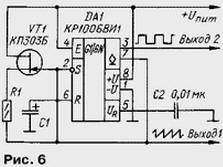
When the voltage is high at the output of timer DA1, transistors VT5 and VT1 are open. Capacitor C1 is charged at the same time through transistors VT1 and VT4. The "current mirror" on transistors VT2 and VT4 provides a current through the capacitor equal to the current generated by the source on transistor VT3. When the timer output is low, transistors VT1, VT2, VT4 and VT5 are closed, so the capacitor is discharged through the collector junction of transistor VT4. The discharge current of the capacitor also sets the current source on the transistor VT3. When implementing this generator, it must be borne in mind that in order to realize all the advantages of the used circuit solution, the "current mirror" transistors must be an assembly on a common chip, otherwise it can give a significant current error (10 or more times) and a strong dependence of current on temperature . The triangular voltage is removed from the capacitor C1 through a follower on a field-effect transistor or on an op-amp. If there is a need for frequency modulation of the generated oscillations, the zener diode VD1 and the resistor R1 are excluded, and the modulating voltage is applied to the base of the transistor VT3. On the timer KR1006VI1, you can also build sawtooth oscillation generators. A diagram of one of these generators is shown in Fig. 6. When a high level voltage is present at the output of timer DA1, capacitor C1 is charged relatively slowly from a current source on a field-effect transistor VT1. As soon as the voltage on the capacitor reaches the level 2Upit / 3, the high voltage level at the output of the timer will change to low and the capacitor will quickly discharge through the open internal transistor of the microcircuit.
The generation frequency is determined by the current I of the source on the transistor VT1 and the capacitance of the capacitor C1. The oscillation period of the generator is equal to T=C1.Upit/(3I) The generator according to the scheme of fig. 5 can also generate a sawtooth voltage - for this, it is enough to connect the output from the OK timer (pin 7) through the contacts of the toggle switch to the inputs R and S. Sawtooth oscillations are removed from output 2. Thus, the generator becomes three-functional. Author: A. Shitov, Ivanovo, Moscow Region
Artificial leather for touch emulation
15.04.2024 Petgugu Global cat litter
15.04.2024 The attractiveness of caring men
14.04.2024
▪ Stanen is a competitor of graphene ▪ 10 Gbps fiber optic transmitters
▪ section of the site Interesting facts. Selection of articles ▪ article Europe can wait. Popular expression ▪ article How do scientists determine the depth of the ocean? Detailed answer ▪ article Weather Records. Heat. Tourist tips ▪ Prostokvash article. Simple recipes and tips
Comments on the article: Jury Thank you exhaustively [up]
Home page | Library | Articles | Website map | Site Reviews
www.diagram.com.ua |


 Leave your comment on this article: