|
|


 Arabic
 Bengali
 Chinese
 English
 French
 German
 Hebrew
 Hindi
Hindi Italian
 Japanese
 Korean
 Malay
Malay Polish
 Portuguese
 Spanish
 Turkish
 Ukrainian
 Vietnamese
|
ENCYCLOPEDIA OF RADIO ELECTRONICS AND ELECTRICAL ENGINEERING A simple CB antenna. Encyclopedia of radio electronics and electrical engineering
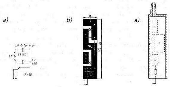
Encyclopedia of radio electronics and electrical engineering / VHF antennas The design of a simple and efficient CB antenna is shown in fig. 13. Here: 1 - antenna carrier - a sliding (telescopic) fiberglass rod 6 ... 8 m long; 2 - thrust bearing; 3 - braces (preferably rigid), fixing the antenna in the desired position; 4 - antenna vibrator - wire MGV or MGSHV with a cross section of 0,5 ... 1,5 mm2 and ~5,37 m long, attached with electrical tape to the end of each rod segment 1; 5 - matching device in a waterproof case; 6 - feeder - 50-ohm coaxial cable; 7 - 5...10 ferrite rings (m=50...2000) pulled over the coaxial cable.
A schematic diagram of the P-loop, matching the high input impedance of the antenna (it is excited in the antinode of the voltage) with a 50-ohm feeder, is shown in fig. 14, a. Coil L1 - frameless. Its 9 turns are wound with PEV-2 1,6 wire on a blank with a diameter of 8 mm and stretched to 19 mm. P-loop capacitors - any high-frequency ones (with low losses at CB frequencies) that have a sufficiently high operating voltage. The latter applies primarily to the capacitor C1*. Its operating voltage Uс1і12(C2/C1)ЦPout, where Pout is the transmitter power in watts, and Uс1 is in volts. So, at Pout = 4 W Uс1і100V, at Pout = 10 W - Us1і160V, and at Pout=100W- Uс1і500 V. And if for a 4 ... 10-watt transmitter, for example, a capacitor of the KCO-1 type (1 V) would be suitable as C250 in the P-circuit, then for a 100-watt transmitter - KSO-2 (500 V) or even higher voltage. The coil and capacitors of the P-circuit are soldered on a single-sided printed circuit board made of foil-coated fiberglass 2 mm thick (Fig. 14, b). The assembled board with the end of the vibrator soldered to it is inserted into a box-case glued from high-impact polystyrene without a "bottom" (Fig. 14, c), protecting it from rain and snow. The antenna feeder is a 50 ohm coaxial cable. With a length of 10 ... 15 meters, it can be quite thin. So, in the PK50-2-16 cable (its outer diameter is 3,5 mm), the losses at CB frequencies will not come out of a negligible 1 ... 1,5 dB. Savings in the weight of the antenna-feeder system can be important, for example, on foot expeditions. It is recommended to take a multiple of the cable length l/2CeWhere l wavelength corresponding to the middle of the operating frequency range, and e- dielectric constant of the coaxial cable dielectric (for polyethylene Tse=1,52). That is, its length can be equal to 3,6; 7,2; 10,8 etc. meters. With such lengths, the cable may even have a different impedance. The antenna is tuned in the usual way. By turning on the SWR meter between the feeder and the radio station, which is transmitting in the middle of the operating frequency range, and shifting and expanding the turns in the P-loop coil (the box cover is shifted to the vibrator), they try to get SWR = 1. If this fails, they look for the frequency (for this you need to have a multi-grid station) at which this happens. If the frequency corresponding to SWR=1 turned out to be below the middle of the operating frequency range, the vibrator is shortened, if it is higher, it is lengthened. The value of elongation-shortening M is calculated from the detuning of the antenna: detuning Df =100kHz corresponds to Dl=2,5 cm.
As experience has shown, the antenna operating frequency band is 300 ... 400 kHz (in SWR <1,5).
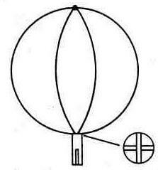
The antenna can be supplemented with a wire "globe" (Fig. 15) made of two 43 cm pieces of steel cable** with a cross section of 0,8 mm2. Their ends, pre-tinned with a good flux, are soldered in a cross-shaped section of the plug socket from the ShR type connector. On the other hand, the end of the vibrator, shortened by 5 ... 10 cm, is soldered into the socket (the desired shortening is specified when tuning the antenna). The "globe" soldered to the vibrator is attached to the very tip of the rod with electrical tape. Lightness and its small windage make such a mount quite sufficient. Antenna with a wire "globe" at the end of the vibrator has a noticeably greater bandwidth and a lower SWR dependence on the operating frequency. In urban conditions, the antenna can be installed directly outside the window of your apartment as shown in Fig. 16 (the antenna is removed from the field of view of the upper windows). The angle between the wall and the rod should be within 20...30°. It is better to put the antenna on the window facing the most interesting correspondents. Of course, the radiation pattern of an antenna installed in this way will be affected by the metal reinforcement of the wall, which shields and absorbs the effect of the entire building. But, as experience shows, its difference from the circular one is largely compensated by the same urban conditions - signal reflections by neighboring buildings. Although the asymmetric radiation pattern in itself is not a drawback of the antenna, of course.
In a village house or in a country house, the antenna can be placed strictly vertically. By inserting, for example, the handle of the rod into a special socket by the attic window. A rod with a vibrator and an antenna box pre-fixed on its sections is moved apart during installation. Another way can be recommended. The handle of a fully deployed rod-antenna is attached with two clamps on the thin end of a 5 ... 6-meter pole. Near the house in the ground, a cylindrical recess is made, according to the diameter of the thick part of the pole, a recess 10 ... 15 cm deep and, inserting the pole into it, raise the entire structure (its weight is 5 ... In the upper part, the pole is attached to any protruding part of the house: it is tied to the roof cornice, to the rafters, etc. In this embodiment, the antenna can be installed outside any buildings, only some other reinforcement of its pole-mast is required. The antenna does not need to be raised if it is mounted on a sliding fiberglass rod 11 ... 12 m long. To fix such an antenna in a vertical position, it is enough to attach it, for example, to the rack of an expedition tent or to a duralumin corner hammered into the ground. If the antenna is deployed at the edge of the forest, then, as a rule, it is possible to use a suitable tree. Through its bough, located at a height of 11 ... 12 m, they throw *** a nylon fishing line, with which they pull the entire antenna system to it - a vibrator with a P-loop box hanging on it and part of the feeder. It is only necessary to leave between the tree itself and the top of the vibrator (having a voltage antinode at this point) a 10 ... 15-cm piece of fishing line as a high-frequency insulator. Height 11...12 m (~l), which was recommended for this antenna in all its variants, was not chosen by chance. With such a height of suspension of a vertical half-wave vibrator above a conducting surface, its radiation at small angles to the horizon, which is necessary for communication with the correspondent by the "ground" wave, reaches a maximum (radiation losses at other angles become minimal). But this is true only for distances between correspondents r not exceeding rmax@ 4(Цh1 +Цh2), where rmax is the maximum distance of “radio visibility” - in km, and h1, and h2 are the heights of the correspondents’ antennas - in m. If r i< rmax, then the antenna is set according to rmax, since the height of the antenna suspension will play a greater role here than the best "pressure" of its radiation lobe to the horizon. If, according to the communication conditions, there is no need to keep the antenna on the street all the time, attracting undesirable, perhaps, attention to it, then among the full-sized antenna described, perhaps, it has no equal: its installation and dismantling takes less than a minute. As shown by long-term tests (with radio stations Yosan-2204, Dragoit SY-101, etc. without any amplifiers), the antenna, both in urban and rural versions, made it possible to keep a confident connection with the "ground" wave at distances up to 30 ...40 km and more. And on the "passage" - with all regions of the European part of Russia, Ukraine and Belarus. *) At higher frequencies, the criterion for choosing capacitors for the antenna circuit is their reactive power and loss tangent. **) Such a cable is used for decorative upholstery of "soft" doors. ***) For example, using a slingshot; the projectile can be a 20 ... 30-gram fishing sinker attached to the end of the fishing line. Publication: cxem.net
A New Way to Control and Manipulate Optical Signals
05.05.2024 Primium Seneca keyboard
05.05.2024 The world's tallest astronomical observatory opened
04.05.2024
▪ MSI G322CQP Concave WQHD Gaming Monitor ▪ Smoking mother harms unborn child ▪ All Samsung electronics will be equipped with artificial intelligence ▪ Toshiba Medium Voltage Photo Switch for Industrial Applications ▪ Microsoft will release a revolutionary smartphone
▪ section of the site Home workshop. Article selection ▪ article Fathers and sons. Popular expression ▪ Article How many calories does a person need? Detailed answer ▪ backpack article. Tourist tips ▪ article A simple VHF receiver. Encyclopedia of radio electronics and electrical engineering
Home page | Library | Articles | Website map | Site Reviews
www.diagram.com.ua |


 Leave your comment on this article: