|
|


 Arabic
 Bengali
 Chinese
 English
 French
 German
 Hebrew
 Hindi
Hindi Italian
 Japanese
 Korean
 Malay
Malay Polish
 Portuguese
 Spanish
 Turkish
 Ukrainian
 Vietnamese
|
ENCYCLOPEDIA OF RADIO ELECTRONICS AND ELECTRICAL ENGINEERING Small-sized antenna of the CB range. Encyclopedia of radio electronics and electrical engineering
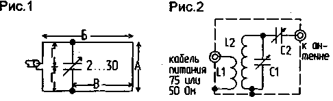
Encyclopedia of radio electronics and electrical engineering / VHF antennas Antenna equipment is a necessary component of any radio station. For a CB radio station, which can be used both mobile - from a car, and stationary - from home, it is necessary to have a permanent “home” antenna. One of the simplest and most effective versions of such an antenna was given in [1], but this antenna works effectively only on the upper floors of buildings. When located on the lower floors, its effectiveness is significantly reduced due to the strong absorption of the vertical component of radiation by nearby houses, which constitute a fairly effective screen. In such cases, a loop antenna works more efficiently. One of the variants of the loop car antenna was considered in [2]. The loop indoor antenna can be located around the perimeter of the window (Fig. 1). The capacitor, which tunes the antenna to resonance, is located on the crossbar dividing the window into two parts.
Two variants of the antenna were tested. Dimensions of the first - A=140 cm, B=140 cm, H=40 cm; D=70 cm. The capacitor was placed in a box made of foil fiberglass; its final capacitance was 3,5 pF. With smaller window perimeter sizes, the capacitance of the capacitor increases. The fact that the capacitor is not located symmetrically, but somewhat to the side of the geometric, and in this case electrical, center of the antenna does not interfere with its normal operation. The second version of the antenna had dimensions A = 140 cm, B = 210 cm, C = 40 cm. In this case, the capacitor was not needed, the antenna was tuned to resonance by conductors G, which in this case were 60 cm long. Both antennas were made of flexible copper wire 1 mm in diameter and located on the inside of the window. It should be noted that for the operation of the antenna there is no difference where it is installed - on the inside or outside of the window, everything determines only the convenience of its installation. Distance B can also be changed with different window options. In the case of a low location of the antenna - on the lower floors, and therefore, if it is necessary to “climb out behind the screen”, the greatest effect is obtained by feeding the antenna either in one of its lower corners, or in the center of its lower side. But in practice, the implementation of such power supply, on the contrary, reduces the efficiency of the antenna compared to power supply in the center of the vertical side. This is due to the fact that under the window there is usually a metal window sill and a heating radiator, which strongly absorb RF energy. If the rooms face different sides of the house, it makes sense to install two antennas, which allows you to confidently work in two directions. Antenna tuning is not difficult and can be done in several ways. The simplest of them is using a field strength indicator. By changing the capacitance of the capacitor or the length of the elements G, it is necessary to achieve the maximum field strength. But more careful tuning is possible only with the help of an SWR meter or an RF bridge, for example, given in [35]. Indeed, by tuning the antenna to the strength indicator and using an industrial CB radio with automatic power control, which most stations are equipped with, it is difficult to achieve correct antenna tuning. Using the same bridge, the input of which is matched with the output of the transmitter, it is possible to carry out a very precise tuning of the antenna to resonance and at the same time determine its real resistance. As it turned out, the resistance of the first version of the antenna was about 55 ohms, the second version - about 50 ohms, in both cases with little reactivity. This shows that both antennas can be powered most efficiently with a XNUMX ohm cable, which is very convenient, because. imported radio stations are designed for such antenna impedance. But the greatest effect when using such an antenna is the use of a matching device (Fig. 2). The device is made asymmetrical, because the loop antenna, although it belongs to the symmetrical ones, but in this case the influence of foreign objects unbalances it. Coil L2 is made of copper wire 1,5 mm thick, frameless. It contains 6,5 turns, diameter - 25 mm, winding length - 40 mm. The cold end is soldered to the bottom of the box, the hot end is soldered to the C1 rotor. Coil L1 contains two turns of the same wire, is located on top of L2 and is located in the lower third of it. This matching device makes it possible to bring the resistance of the indoor loop antenna from the side of the input of the matching device (SU) to any resistance of a standard cable - 50 or 75 Ohm, while there was practically no reactive component. The matching device operates with a high efficiency - at least 90% (practically measured), so that almost all the power from the transmitter goes to the antenna. Being a narrowband circuit, the SU effectively eliminates TVI, which is especially important when using a radio with a power amplifier. This version of the control system can be configured so that it will work in the entire MW range with a small SWR at its edges. The matching device was made in a box of foil fiberglass with dimensions of 6x8x6 cm and placed in close proximity to the antenna. Rotors C1 and C2 were brought outside for adjustment. It should be noted that the use of SU, which makes it possible to achieve SWR in the cable feeding the antenna, almost 1:1, makes it possible to safely apply various noise filters repeatedly cited in the literature (for example [4,5, XNUMX]), which can reduce the TVI level very significantly . The filter must be installed immediately at the output of the radio station. In a comparative test of the loop antennas described in this article with the antenna from [1], their clear advantage was revealed. Loop antennas provided longer communication range and much lower TVI and radio interference. The latter is especially noticeable when using a matching device. More importantly, these loop antennas can be placed almost imperceptibly, which does not spoil the interior of the room. The trimmer antenna is well matched in the frequency range from 21 to 30 MHz, which makes it possible to work not only in the MW band, but also in several amateur HF bands. The matching device with the ratings of the radio components indicated here matches well only from 30 to 24 MHz. To operate at 21 MHz, the capacitances of capacitors C1 and C2 must be increased to 50 pF, or the number of turns of the coil L2 must be increased to 8,5, while maintaining the length of the winding. In this case, the upper operating frequency of the control system is limited to 29 MHz. The second antenna, when used with a variable capacitor, covered the range from 14 to 24 MHz. Coil L2 of the matching device for this range should contain 11,5 turns with a winding length of 45 mm. The coupling coil in all cases contains 2,5 turns. It can be moved around the loop coil to find the optimum connection and optimum SWR. In all cases, when setting up the SS, one should strive to ensure that the final capacity of C2 is the maximum possible. The minimum value of C2 indicates an incorrect setting of the cable - SU - antenna system. At powers above 10 watts, high RF voltage may be present on the antenna capacitor, so measures should be taken to electrically isolate it. Literature
Author: I. Grigorov (RK3ZK, UA3-113); Publication: cxem.net
A New Way to Control and Manipulate Optical Signals
05.05.2024 Primium Seneca keyboard
05.05.2024 The world's tallest astronomical observatory opened
04.05.2024
▪ Smart car video processor GEO GW5 ▪ A smartphone with a 3D space modeling system from Google ▪ A new method for determining the age of complex deposits ▪ The nature of the influence of plants on stress ▪ Xbox One with overheating protection
▪ section of the site for the Musician. Selection of articles ▪ Disket article. History of invention and production ▪ article How do scientists determine the depth of the ocean? Detailed answer ▪ article Head of the Department (Editorial, Television, Radio Broadcasting). Job description ▪ article High-speed surge protection. Encyclopedia of radio electronics and electrical engineering
Home page | Library | Articles | Website map | Site Reviews
www.diagram.com.ua |

 Leave your comment on this article: