|
|
ENCYCLOPEDIA OF RADIO ELECTRONICS AND ELECTRICAL ENGINEERING balanced modulator. Encyclopedia of radio electronics and electrical engineering
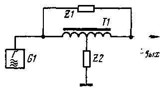
Encyclopedia of radio electronics and electrical engineering / Knots of amateur radio equipment. Modulators To obtain amplitude-modulated oscillations with a suppressed carrier in communication technology, diode balanced and ring modulators are usually used. They work great at relatively low frequencies, but at frequencies above 10 MHz, such modulators suffer from balancing accuracy and, accordingly, carrier suppression. This is due to the difficulty of selecting diodes with identical characteristics and the harmful shunting effect of diode capacitances that increases at HF. The proposed balanced modulator (Author's certificate No. 627560. Bulletin No. 34 dated 5.10.78) is largely devoid of this drawback. It is made according to the T-shaped bridge scheme (Fig. 1). The T-bridge itself contains a symmetrical high-frequency transformer T1 and two resistances Z1 and Z2. They can be either active or reactive (inductive or capacitive). The transfer coefficient (the ratio of the output voltage Uout to the voltage developed by the carrier generator G1) of the T-bridge is zero under the condition Z1= =4Z2. If the resistance Z2 is increased. at the output of the bridge A voltage appears that is in phase with the voltage of the generator, since the current in the longitudinal branch of the bridge containing Z1 will prevail. If the resistance Z2 is reduced, then the current flowing through the left (according to the circuit) half of the winding of the transformer T1 and the transverse branch - the resistance Z2 will prevail. At the output in this case, a voltage will appear, induced in the right half of the winding, and antiphase to the generator voltage. Thus, by changing the resistance of one of the arms of the bridge in time with the audio frequency, you can get a DSB signal.
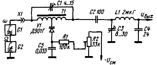
A practical diagram of a modulator operating at a carrier frequency of 28 MHz is shown in fig. 2. The resistance of the longitudinal branch 7.1 is capacitive
the resistance of the capacitor C1, and the transverse Z2 is the capacitance of the varicap V1. The mixing voltage is supplied to the varicap from the trimmer resistor R2, which balances the modulator. If the bias source has a negative terminal connected to the common wire, then the inclusion of the varicap should be changed to the opposite. The capacitance of the capacitor C / must be four times less than the capacitance of the varicap at a given mixing voltage. When a sonic modulating voltage is applied to the varicap. its capacitance changes and the T-bridge is unbalanced in one direction or another, providing amplitude modulation with carrier suppression. Carrier and audio frequency voltages are applied to the modulator (generators G1 and G2 can, in principle, be connected both in series and in parallel). In this case, the input impedance for the audio frequency is very large and reaches tens of megaohms. Thanks to this, the modulator can be connected to any high-resistance G2 low-frequency signal source, for example, an RC phase shifter (when designing a phase SSB exciter). The modulating voltage can also be applied in a different way: to the upper terminal of the capacitor C5, reducing its capacitance to 1000 ... 3000 pF in order to avoid blocking the higher sound frequencies. The input resistance will then be equal to the resistance of the mixing circuit resistor R1. The engine of the variable resistor R2 should be connected to a common wire through a capacitor with a capacity of 0.1 ... 10 microfarads. The input resistance of the modulator for the carrier frequency generator G/ is much less. it is capacitive in nature and is approximately 200 ohms.
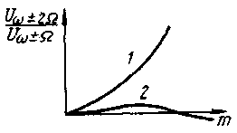
Coupling capacitor C2 prevents sound voltage from entering the modulator output. To match the modulator with the load, the LIC3C4 P-loop is used, tuned to the signal frequency. With the ratings of the capacitors shown in fig. 2, the modulator is in good agreement with a high-resistance load (an amplifying stage made on a lamp or a field-effect transistor). To match with a low-resistance load, a larger capacitor C4 should be used, achieving maximum power output of the modulated signal. The P-loop provides good filtering of carrier harmonics with frequencies of 2f, 3f, etc. By adjusting this loop, you can also achieve good linearity of the modulator. Nonlinear distortions during the operation of the modulator on an active load appear as follows: the amplitude of the output signal with a negative half-wave of the modulating voltage (when the capacitance of the varicap increases) is somewhat greater than with a positive one. This is equivalent to the appearance of the second harmonic of the modulating signal. The occurrence of distortions is explained by a decrease in the internal capacitance of the modulator with an increase in the capacitance of the varicap. With an increase in the modulation factor m, the nonlinear distortions increase noticeably (curve 1 in Fig. 3). The corresponding waveform of the output signal is shown in fig. 4a.
The described distortions are almost completely eliminated with a slight detuning of the output circuit up in frequency. when its resistance becomes inductive. With further detuning, similar distortions appear (but another half-wave of the modulated signal decreases). Thus, by adjusting the circuit with capacitor C3, very small non-linear distortions can be achieved (curve 2 in Fig. 3 and the oscillogram in Fig. 4, b). With a properly tuned circuit, the instantaneous value of the harmonic coefficient in the worst case (the amplitude of the low-frequency signal is such that the modulation coefficient m corresponds to the maximum of curve 2 in Fig. 3) does not exceed 2...3%. The balancing of the modulator when adjusting the contour is not disturbed. In the modulator, you can use any type of varicap with a nominal capacitance of at least 30 pF. Transformer T1 is wound on a ring core (size K8x4x2) made of M100NN ferrite and contains 2x10 turns of PELSHO 0,25 wire. You can use other ferrite ring cores with a permeability of 30 to 400. Both halves of the transformer winding are wound simultaneously with two wires folded together. Then the beginning of one of them is connected to the end of the other, forming the middle conclusion. Coil LI contains 20 turns of the same wire wound on a cylindrical frame (tube) with a diameter of 6 mm. Setting up the modulator is easy. By setting the bias voltage on the trimmer resistor R2 to about 6 V, roughly balance the modulator with capacitor C1 to a minimum of the carrier signal at the output. Fine balancing is achieved by adjusting the resistor R2. Then, having applied a low-frequency signal, they observe the shape of the output voltage using a high-frequency oscilloscope (see Fig. 4) on the capacitor C4 I adjust the output P-circuit to the maximum amplitude and minimum distortion. You can set up the modulator without an oscilloscope, listening to the signal on the communication receiver. But in this case, the adjustment of the elements C1 and R2 is carried out according to the minimum carrier, and C3 - according to the best quality and loudness of the signal. Experimental verification of the modulator was carried out at a carrier frequency of 28 MHz. The carrier frequency voltage amplitude was 1 V, and the low-frequency signal amplitude was 4 V. In this case, an output signal amplitude of 0,35 V was obtained with carrier suppression of at least 30 dB (the minimum value that the author could register with his measuring equipment). In conclusion, it should be noted that the modulator can be used to obtain not only a DSB signal, but also a conventional amplitude modulated one, by greatly unbalancing it with the capacitor C1 and. thus restoring the carrier. In this case, you can get very deep AM (almost 100%) with low distortion. Author: A.Polyakov (RA3AAE), Moscow; Publication: N. Bolshakov, rf.atnn.ru
Machine for thinning flowers in gardens
02.05.2024 Advanced Infrared Microscope
02.05.2024 Air trap for insects
01.05.2024
▪ Sounds of nature are good for health ▪ Drinks with a sour taste make people take risks ▪ Chainsaw with microprocessor ▪ Nanomaterial for cleaning air on submarines
▪ section of the website Residual current devices. Selection of articles ▪ article Simulator - glider flight simulator. Tips for a modeler ▪ article What technical product is the most massive in the history of mankind? Detailed answer ▪ article Work with a manual scythe. Standard instruction on labor protection ▪ article Economic photorelay. Encyclopedia of radio electronics and electrical engineering ▪ Tachometer article. Encyclopedia of radio electronics and electrical engineering
Home page | Library | Articles | Website map | Site Reviews www.diagram.com.ua |


 Arabic
 Bengali
 Chinese
 English
 French
 German
 Hebrew
 Hindi
Hindi Italian
 Japanese
 Korean
 Malay
Malay Polish
 Portuguese
 Spanish
 Turkish
 Ukrainian
 Vietnamese


 Leave your comment on this article: