
|
|
ENCYCLOPEDIA OF RADIO ELECTRONICS AND ELECTRICAL ENGINEERING Power supply of fluorescent lamps from low-voltage DC voltage sources. Encyclopedia of radio electronics and electrical engineering
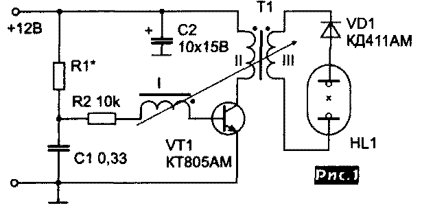
Encyclopedia of radio electronics and electrical engineering / Lighting Due to interruptions in the supply of electricity, many problems arise in ensuring the operability of radio and television equipment, computers, lighting, etc. It is especially troublesome to lose power during extreme situations, for example, when doctors are fighting for a person's life, or when urgent emergency work is urgently needed, etc. One of the most accessible ways to ensure uninterrupted power is the transition to those electrical appliances that, according to technical and operational characteristics, can operate from autonomous sources of electricity that are charged or maintained in a charged state during normal power supply. The main and affordable means are rechargeable batteries, from which you can directly power incandescent lamps with a voltage of 6, 12, 24 V, car electronics, radios, TVs, watches, computers and much more. Equipment operating from 220 V AC can be powered by converters (12-220/110 V), (24-220/110 V). This article proposes three converter circuits designed to power fluorescent lamps with a power of 4-10 W from a 12 V DC source. -6, LEC2, LBE4, LB2-4, and with foreign Philips TL7W / 6, TL7W / 8, TL1W / 8, TL10W / 18. TL1W/6 etc. Similar circuits are used in imported portable battery-powered lamps and, despite their simplicity, have high technical characteristics. Description of the principle of operation When voltage is applied to the circuit (Fig. 1), a current will flow through the resistor R1, limited in value by the resistance R1, and the capacitor C1 will be charged. Upon reaching a voltage of about 0,6 V at the same time on the base of the transistor VT1 and capacitor C1, the transistor will avalanche-like enter saturation mode due to the deep positive feedback between the base and collector of the transistor VT1 through the base and inductively coupled collector windings of the transformer T1. From this moment, the current increases in the collector circuit according to a linear law, described by the formula (dIk / dt) L \u1d U. At the same time, the base current of the transistor VT1 decreases due to the overcharging of the capacitor CXNUMX. When the inequality Ik > h21e Ib is reached, the transistor VT1 will avalanche-like leave the saturated state. At the same time, the inductance of the collector winding of the transformer T1, trying to provide a current in the collector circuit of the transistor VT1 and interacting with the high-impedance state of the circuit elements, will create a voltage surge that is dozens of times greater than the supply voltage, and on the secondary winding in K = Wl / Wk times, where : Wl - the number of turns of the output winding, Wk - the number of turns of the collector winding. Due to these voltage surges, reaching 1000 V in magnitude, the lamp is ignited, as a result of which its internal resistance decreases sharply and with it the voltage drop across it, approaching the operating voltage for which the type of lamp used is designed.
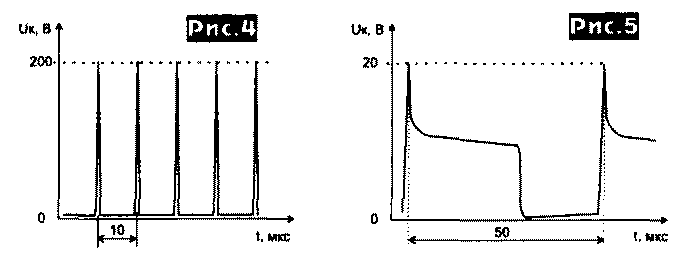
In the process of prototyping and debugging the circuit, oscillograms of the collector voltage were taken and are presented in Figs. 4 and 5. The amplitude of voltage surges (Fig. 4) is limited in the collector winding circuit by a current within the boundary voltage of the applied transistor VT1 and in the base winding circuit by the Zener breakdown current of the junction base-emitter VT1. Figure 5 shows a sharp decrease in the magnitude of the pulse voltage on the collector of the transistor VT1, since the secondary winding of the transformer T1 after a gas breakdown in the HL1 lamp was loaded with low internal resistance, determined by the current-voltage characteristic of the type of lamp used. It is difficult to overestimate this simple blocking oscillator circuit, which automatically adapts to changing loads, and, despite some shortcomings, it can be called a "miracle" of impulse technology.
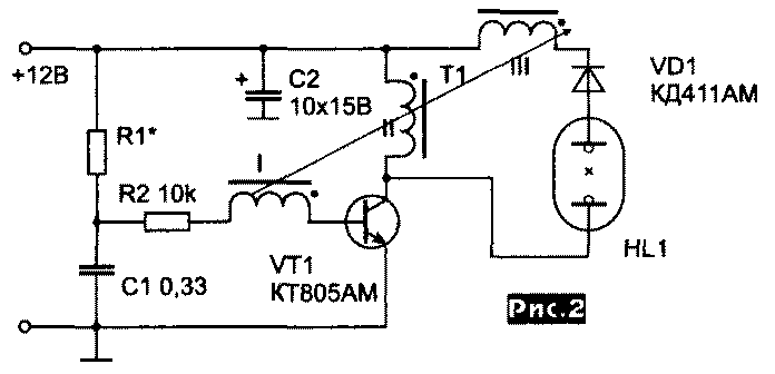
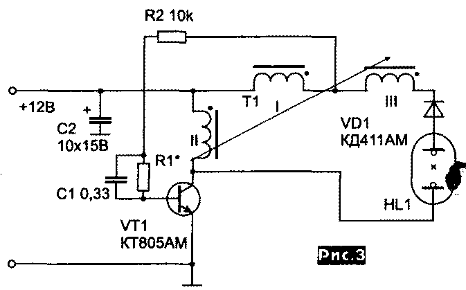
The scheme presented in Fig. 2 allows you to successfully combine the relationship of the elements of the scheme with its design. The reflector of the lamp, made of shiny metal and connected to the VT1 collector, simultaneously functions as a radiator and conductor for better ignition of the lamp, and also allows you to connect the lamp electrodes without additional wire. The manufacture of the T1 transformer is simplified, since two windings are connected in series to the lamp - a collector and an output, which has fewer turns for their number, which contains the collector winding. The circuit in Fig. 3 differs from the previous ones in the placement of the base winding, and as a result, the collector, base, and output windings are connected in series and connected to the lamp. This made it possible to simplify the design and facilitate the manufacture of the transformer T1. Instead of six conclusions, as in the circuit in Fig. 1, only three. All three windings are involved in creating the output voltage on the lamp. Just as in the previous diagram, the design of the reflector for the HL1 lamp, the radiator for the VT1 transistor, and the conductor for connecting the lamp electrode is performed by the same part. This scheme is the most technologically advanced and less time-consuming.
Construction and details The radio elements of the circuit, namely the transformer T1, resistors R1, R2, capacitor C1, diode VD1 can be placed on a foil-lined fiberglass board, and with the simplicity of the circuit, the board can be easily made by mechanically removing the foil with an unpretentious pattern configuration. Transistor VT1 must be installed on a heat sink with an area of \u20b\u2b\u1e 1 cm200, which is suitable for design, the shape and dimensions of which will be determined by the type of lamp used and the design of the case. As mentioned above, it is most convenient to combine a reflector, a radiator, an ignition electrode, a conductor for connecting a lamp in one part. Transistor VT21 must have sufficient speed (t race <20 ms), while the boundary voltage must be U gr.> 1 V, the current gain in the circuit with a common emitter h 0,8e > 1,5. The magnitude of the pulsed currents at which the transistor VT21 Ik \u1d (5 - XNUMX) A will work, and it is necessary that such currents be in the increasing section of the characteristic nXNUMXe (XNUMXk). It is desirable to use transistors with the highest possible reverse base-emitter voltage Ube> XNUMXV. These parameters must be taken into account when repairing imported fixtures. Satisfactory results were obtained using transistors KT847A, KT841A, KT842A, from inexpensive ones - KT805AM. In the process of circuit layout, several transformer designs were tested. The best results were obtained when using armored cores made of M2000NM grade ferrites, sizes B26, BZO, 536 and W-shaped with a section of 7x7 made of ferrite 4000. When assembling transformers, it is necessary to provide a non-magnetic gap h = 0,025 ... 0,1 mm to prevent magnetization of the magnetic circuit . A larger gap leads to a sharp decrease in the inductance of the transformer T1, which will worsen the operating conditions of the circuit. On the plastic frame, the collector winding is first wound with a PEV 0,4 wire, then an insulation layer is laid and the base winding is wound with a PEV 0,2 wire. A layer of varnished fabric or fluoroplastic tape is laid over the base winding and the secondary winding is wound with PEVTL-2 wire with a diameter of 0,15 ... 0,2 mm, turn to turn and with layered insulation. Approximately the number of turns of the windings can be selected, guided by table 1.
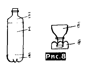
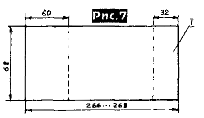
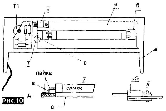
The secondary winding can be made universal with taps every 30...50 turns. The VD1 diode is necessary in order to, participating in the self-oscillating process, give off the energy accumulated by the inductance of the collector winding of the transformer T1 during periods of the off state of the transistor VT1. This allows you to adapt the circuit to different loads and use different current sources. In this case, instead of the resistor R1, it is necessary to connect two resistors - one constant with a resistance of 430 Ohms, and the second variable with a resistance of 2,2 kOhm connected in series. Diode VD1 must be designed for voltage Uobr. > 200V, have operating frequency fp. > 100 kHz, average rectified current Icp. > 200 mA. In addition to those indicated in the diagram, four diodes of the KD 510A type can be used by connecting them in series. The design of the fluorescent lamp is made of items that are often filled with a trash can in everyday life. The housing (Fig. 6, Fig. 10) is made from a used EPSON Mx80/Fx80 type cartridge, inside of which the partitions must be removed. You can also use a suitable aluminum or plastic profile, etc. The front transparent screen is made of a PEPSI plastic bottle or any other 2 liter bottle with straight sides. Dimensions are shown in fig. 7. It is advisable to use a light color without shades and scratches. On fig. indicates the part that needs to be cut out of a plastic bottle to make a transparent screen.
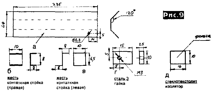
From the remaining two parts, using imagination, you can make a stand for pencils, pens or a glass for watering flowers, etc. Figure 7 shows the areas bounded by dotted lines that need to be sealed with pieces of thin black plastic cut out of cases from old computer floppy disks (5,25) with Moment-type glue. On fig. 9 shows a drawing of a reflector-radiator, which is cut out of tin using Nescafe or Monterey coffee cans with a capacity of 250 gr.
The reflector (a) is glued to the cartridge body (e) using Moment glue. A transparent screen (Fig. 7, Fig. 10) is bent along the long side and inserted into the gap between the reflector (a) and the body (e), in which four holes with a diameter of 1,2 ... 2 mm are drilled together with a transparent screen, and fastened with four screws or screws of the appropriate diameter. Spring clips, loops, a magnet, etc. must be provided for fixing the luminaire under various conditions. It is possible to additionally adapt the lamp as part of a table lamp, headlamp, etc. After assembling the circuit and connecting it to a power source, it starts working immediately, provided that the installation is completed without errors and all parts are known to be in good order. Connect an ammeter to the circuit between the power source and the lamp circuit and adjust the current consumption by resistor R1. For economical operating modes, it is necessary to set the consumption current within 120 ... 200 mA, but if a sufficiently energy-intensive source is used, the consumed current can be increased to 500 mA, thus obtaining a greater luminous flux. If it is necessary to use the lamp in different operating modes and from different sources of electricity, it is necessary to install two resistors connected in series, one of which is variable, instead of resistor R1. The resistance values are given above in the text. Thus, you will be able to smoothly adjust the luminous flux.
In all three diagrams, Fig. 1 - Fig. 1 of the article, the value of the resistors R1 is incorrectly indicated; should be R10=47...XNUMX Ohm. Literature 1. A. Khalatyan. Supply of fluorescent lamps. Moscow, DOSAAF USSR, 1979, VRL No. 67 p. 33.
Author: Taras Kholoptsev, Kiev, Radiohobby; Publication: N. Bolshakov, rf.atnn.ru
Air trap for insects
01.05.2024 The threat of space debris to the Earth's magnetic field
01.05.2024 Solidification of bulk substances
30.04.2024
▪ Micro-objects are visible behind the wall ▪ The most relevant brands of our time
▪ section of the site Life of remarkable physicists. Article selection ▪ article Wild people! Mountain children. Popular expression ▪ What were ships made of in ancient Egypt? Detailed answer ▪ article Making cold. Children's Science Lab ▪ article Depth metal detector. Encyclopedia of radio electronics and electrical engineering
Home page | Library | Articles | Website map | Site Reviews www.diagram.com.ua | |||||||||||||||||||||||||||||||||||||||||||||||


 Arabic
 Bengali
 Chinese
 English
 French
 German
 Hebrew
 Hindi
Hindi Italian
 Japanese
 Korean
 Malay
Malay Polish
 Portuguese
 Spanish
 Turkish
 Ukrainian
 Vietnamese
 Leave your comment on this article: