|
|


 Arabic
 Bengali
 Chinese
 English
 French
 German
 Hebrew
 Hindi
Hindi Italian
 Japanese
 Korean
 Malay
Malay Polish
 Portuguese
 Spanish
 Turkish
 Ukrainian
 Vietnamese
|
ENCYCLOPEDIA OF RADIO ELECTRONICS AND ELECTRICAL ENGINEERING Reflex radio. Encyclopedia of radio electronics and electrical engineering
Encyclopedia of radio electronics and electrical engineering / Beginner radio amateur [an error occurred while processing this directive] The detector receiver allowed you to practically become familiar with the principles of receiving signal broadcasting radio stations and extracting audio frequency oscillations from them. The next step has also been made - an amplifier for the receiver has been made in order to increase the sound volume. The result is a direct amplification receiver. A reflex receiver can be considered a variation of such a design, in which the same cascades perform a dual function - they amplify both the radio frequency signal and audio frequency oscillations. Some versions of such a receiver are described in the proposed selection. Reflex on one transistor A single-transistor reflex receiver with a magnetic antenna is quite suitable for receiving powerful nearby radio stations in the DV range (Fig. 1).
The oscillatory circuit of the magnetic antenna is formed by a coil L1 and a variable capacitor C1. The radio frequency (RF) oscillations allocated by him need to be amplified, but it makes no sense to directly connect the circuit to the amplifier. Due to the low input impedance of the amplifier, the selectivity of the circuit will deteriorate sharply and the receiver will be unable to "select" the desired radio stations from those located close in frequency - they will be listened to at the same time. To avoid this, the RF oscillations are fed to the amplifier through coil L2, which is inductively coupled to the loop coil. The number of turns of the coupling coil is tens of times less than the contour coil, and the signal on it is the same number of times less than the signal on the oscillatory circuit. But this signal attenuation is compensated by the RF amplifier. The signal amplified by the cascade on the transistor VT1 is emitted by the coil L3 of the high-frequency transformer and through the coil L4 enters the detector, the role of which is performed by the diode VD1. The load of the detector is the emitter junction of the transistor (base-emitter section), the capacitor C2 "cuts off" the RF oscillations. The 3H oscillations obtained as a result of the detection are amplified by the transistor cascade and fed to the BF1 headphones. The bias voltage to the base of the transistor is supplied through the resistor R1, which is a simultaneous element of the filter R1C3, which prevents 3H oscillations from phones from entering the base of the transistor. Coils L1 and L2 can be wound on a paper frame located on a flat or round rod of 600NN ferrite (such rods are used in industrial small-sized transistor receivers): L1 contains 100 ... 150 turns of wire of the PELSHO, PEV or PEL brands with a diameter of 0,1. ..0,12 mm, L2 - 15...20 turns of the same wire. Coils L3 and L4 are also wound with the same wire, but on a ferrite ring with an outer diameter of 10 and a thickness of 5 mm (size K10x6x5). Each coil should contain 180 turns, evenly spaced along the entire length of the ring. Instead of the transistor indicated on the diagram, KT315G, KT315E with a base current transfer coefficient of 100 ... 150 are suitable. Diode - any of the D9 series. Capacitor C1 - with the largest capacity of 350 ... 400 pF. If there is a two-section capacitor of smaller capacity, its sections are connected in parallel. Capacitor C2 - BM, MBM, KM or another type, C3-K50-ZA or similar oxide. Headphones - TON-1 or TON-2, power source - any galvanic cell. If the parts are connected during installation in accordance with the diagram, the receiver, as a rule, starts working immediately after switching on. It is possible that self-excitation in the form of a whistle will immediately appear, then you will have to swap the inclusion of the leads of one of the transformer coils. After that, you need to tune the receiver to some radio station and try to choose a resistor R1 of such a rating at which the sound volume in the phones will be the highest. For a while, this resistor can be replaced with a variable, with a resistance of 150 or 220 kOhm, and choose the best operating mode for the transistor. And then measure the resulting resistance and solder a constant resistor of this or possibly a close value to the receiver. Two-transistor reflex with a printed circuit board This receiver (Fig. 2) is much more sensitive than the previous one. Considering that each transistor in it performs a dual function, we can say that the receiver is, in fact, a four-transistor one. True, in comparison with the previous one, it is designed to receive one of the most popular radio stations, for example, "Mayak", which made it possible to make the receiver very small in size.
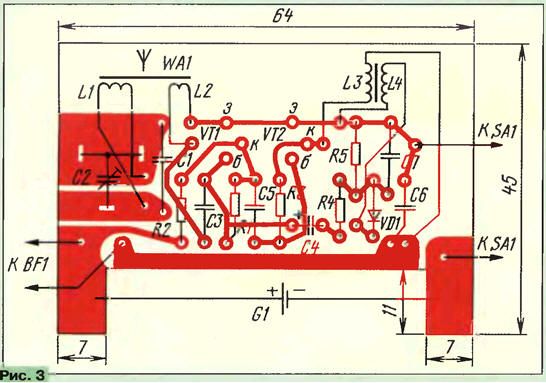
As in the previous case, reception is carried out on a magnetic antenna. The oscillatory circuit is made up of an inductor L1, a capacitor of constant capacitance C1 and a trimmer C2. The first set the resonant frequency of the circuit corresponding to the frequency of the received radio station, the second is more accurately tuned to the station. Although it is not necessary to use a trimmer capacitor. From the terminals of the coupling coil L2, the signal selected by the oscillatory circuit enters through the capacitor C3 to the first RF amplification stage - it is assembled on the transistor VT1. The bias voltage is applied to the base through resistor R1. The radio frequency signal amplified by the first stage is selected at the load resistor R2 and fed from it through the capacitor C5 to the next amplification stage, assembled on the transistor VT2. As in the first stage, the bias voltage at the base of the transistor is formed due to the inclusion of a resistor (R3) between the base and the collector. There are two loads in the collector circuit of this transistor: one for radio frequency, the other for audio frequency. Coil L3 serves as a radio frequency load, since the upper output of the coil according to the circuit is "grounded" by radio frequency (i.e. connected to a common wire - the negative circuit of the power source) through capacitor C6. The signal selected by the L3 coil is transformed (as in a magnetic antenna) and fed through the L4 coil to the detector - diode VD1. The load of the detector is the resistor R5 - it is on it that 3H oscillations are emitted. And the radio frequency oscillations remaining after detection are closed to a common wire through capacitor C7. So, a 3H signal appeared at the output of the detector, but it is weak and cannot be sent to the head phone. Therefore, it enters a transistor amplifier, which now acts in a second role - a 3-hour signal amplifier. In the signal circuit there is a chain of series-connected resistor R4 and capacitor C4. The capacitor is used for DC decoupling of the base and detector circuits. And the resistor allows you to choose such a connection between the detector and the amplifier, which produces the highest sound volume and there is no self-excitation. The 3H signal amplified by two cascades is emitted on the winding of the head phone, which presents much more resistance to these oscillations compared to the L3 coil. From the phone and hear the transmission of the radio station. It's time to talk about the details of the receiver. Transistors must be of the KT315 series with letter indices B, G, E and a static base current transfer coefficient of about 100. Diode - any of the D9 series. For the manufacture of a magnetic antenna, you will need a segment of a rod with a diameter of 8 and a length of 50 mm made of ferrite 400NN or 600NN. A paper frame 40 mm long is put on the rod. At one end of the frame, a coil of connection L2 is wound round to round - 15 turns of wire of the PEV brand with a diameter of 0,15 mm. The remaining surface of the frame is filled with a coil L1, winding in bulk 220 turns of the same wire. With such antenna data, you can receive a radio station in the LW range. If a powerful radio station in the CB range works in your area, the number of turns of the loop coil should be reduced to about 120 ... 100 (more precisely, they are selected during adjustment). Coils L3 and L4 of the transformer are wound on a ferrite ring with an outer diameter of 7, an inner diameter of 4 and a thickness of 2 mm (in the reference literature, such a ring is designated K7x4x2). Ferrite must be 400HN or 600HN. Coil L3 contains 65 turns, and L4 - 170 turns of PEV or PELSHO wire with a diameter of 0,1 mm. The wire is wound evenly along the entire length of the ring. Trimmer capacitor C2 - small-sized type KPK-MP or KPK-MN with a nominal capacity (it is indicated on the capacitor case) 6 ... 25 or 8 ... 30 pF. Oxide capacitor C4 - K50-6, K53-6 or other small-sized, with a capacity of 1 to 10 microfarads for any voltage. The remaining capacitors are of any type, possibly smaller, for example, KM-5, KM-6. All resistors are BC or MLT with a power of 0,125 or 0,25 W. Headphone - TM-2A or similar, with a resistance of 65-200 ohms. Power switch SA1 - miniature of any design. Power source - galvanic cell size AA, for example 316. The details of the receiver, except for the power source, switch and head telephone, are mounted on a printed circuit board (Fig. 3) made of one-sided foil fiberglass. If there is no such material, take an ordinary fiberglass, getinaks or other similar insulating material 1 ... 1.5 mm thick, drill the holes shown in the figure, insert the leads of the parts into the holes and connect them together with conductors imitating colored areas and thickened lines.
In the presence of foil material, it is not at all necessary to etch the paths shown on the foil. You can simply cut the insulating grooves, for example, with a sharp penknife or a special cutter made from a piece of a hacksaw blade. The end of the segment is made rounded and sharpened so that it can scratch the foil on the board. The board is inserted inside the packaging plastic box from under the miniature head phone (Fig. 4). The switch is fixed on the side wall of the case, the wires from the head phone are led out through the groove in the back wall of the case. You can, of course, install a miniature connector on the case and connect the phone to the receiver through it. The power supply is inserted between the contact plates (made of copper or tin) soldered to the corresponding foil pads of the board.
Before mounting the parts on the board, it is advisable to assemble the receiver on a breadboard (or on a regular cardboard) and check its operation, and at the same time tune it to the desired radio station. After mounting the parts, instead of capacitors C1 and C2, a variable capacitor of any type of 350 ... 450 pF is first connected to the terminals of the loop coil (this is its maximum capacitance). After turning on the power, this capacitor is tuned to a well-audible radio station, for example, "Mayak". In this case, the condenser rotor should be approximately in the middle position. If it turns out to be closer to the position of the minimum capacity (i.e., withdrawn), part of the turns should be unwound from the contour coil of the magnetic antenna. Then, orienting the antenna in a horizontal plane, achieve the highest sound volume. You can try to get even more volume by selecting resistors R1, R3, R4. Whenever soldering resistors, the receiver power must be turned off. It remains to measure the resulting capacitance of the capacitor as accurately as possible and connect a constant capacitor of approximately the same capacitance, as well as a tuning capacitor, to the terminals of the loop coil. With an accurate selection of a constant capacitor, you can not install a tuning capacitor at all (it is not in Fig. 4), but tune in to the radio station by moving the coil frame along the ferrite rod of the antenna. Now you can transfer the parts to the board and finally assemble the receiver. Author: V.Polyakov, Moscow
Artificial leather for touch emulation
15.04.2024 Petgugu Global cat litter
15.04.2024 The attractiveness of caring men
14.04.2024
▪ An artificial synapse for an artificial brain ▪ AMOLED with a large diagonal ▪ With age, memory begins to work differently.
▪ site section Tone and volume controls. Article selection ▪ article by Finlay Peter Dunn. Famous aphorisms ▪ article What is yellow fever? Detailed answer ▪ article Electrician on duty at a 10/0,4 kV substation. Standard instruction on labor protection ▪ article PVC insulating tubes. Encyclopedia of radio electronics and electrical engineering
Home page | Library | Articles | Website map | Site Reviews
www.diagram.com.ua |


 Leave your comment on this article: