|
|


 Arabic
 Bengali
 Chinese
 English
 French
 German
 Hebrew
 Hindi
Hindi Italian
 Japanese
 Korean
 Malay
Malay Polish
 Portuguese
 Spanish
 Turkish
 Ukrainian
 Vietnamese
|
ENCYCLOPEDIA OF RADIO ELECTRONICS AND ELECTRICAL ENGINEERING Probe generator - amplifier. Encyclopedia of radio electronics and electrical engineering
Encyclopedia of radio electronics and electrical engineering / Beginner radio amateur There are many probes that hams use for quick checks and when setting up radio equipment. The proposed version is original in that it contains two structures in one housing - an AF signal generator and an amplifier of such signals, which greatly expands the capabilities of this "measuring device". When establishing and repairing various sound amplifying equipment, AF signal generators are often used, and in most cases it is enough to have a generator with a fixed frequency - about 1000 Hz. It can be made in the form of a probe or a probe. Similar constructions were described in [1-4]. There are cases when, in addition to the AF generator, you need a simple amplifier that allows you to check the presence of a signal, say, at the output of a detector, preamplifier, etc. It can also be used to identify a stage that introduces strong distortion, or a stage with a very low gain. That's why I decided to develop a probe that includes both devices (Figure 1). It is designed to be powered by the design under test, so the range of supply voltages indicated in the diagram is very wide. Of course, the option of using an autonomous source, say, with a voltage of 6 V, is not excluded.
The frequency of the AF generator is chosen equal to 1000 Hz, the amplitude of the output signal on the probe probe can be within 0...1 V. The sensitivity of the AF amplifier is 50 mV. The probe contains a voltage stabilization unit, a generator and an AF amplifier. The stabilization unit includes a VD1 diode that protects the probe from erroneous voltage supply of reverse polarity. A current generator is made on the transistor VT1 and diodes VD2, VD3, and a voltage regulator is made on the zener diode VD4 and transistor VT2. The HL1 LED turned on at the output of the stabilizer signals the supply voltage to the generator and amplifier. On the elements DD1, DD2, a generator of rectangular pulses [3] is assembled, which are then "smoothed" to sinusoidal oscillations by the primary winding (with a large number of turns) of the transformer L1. From the secondary winding (small number of turns), the signal is fed to the SA1.1 contact group of the SA1 operating mode switch. In the position of the contacts shown in the diagram, corresponding to the "Generator" mode, the signal follows further to the variable resistor R6 (this is the amplitude control of the output signal of the probe), and from its engine to the emitter follower, made on the transistor VT3. From the load resistor of the repeater R8, the signal follows further to the power amplifier (transistors VT4-VT6). Diodes VD5, VD6 prevent the appearance of "step" type distortions, the resistor R10 helps to stabilize the operation mode of transistors in direct current. The output of the amplifier is connected by a group of contacts SA1.3 either to the X3 probe or to the dynamic head BA1 (when the movable contact is in the lower position according to the diagram). If you need to use a generator, the switch is set to the position shown in the diagram, and the HZ probe touches the terminals of the parts of the cascades under test. The passage of the signal is checked on an oscilloscope or by ear. When an amplifier is needed, the switch knob is moved to another position. The HZ probe also touches the conclusions of the parts, and by the sound in the head they control the presence of the AF signal and its passage through the cascades of the radio device. In addition to those indicated in the diagram, it is permissible to use transistors KT2G, KT817A in place of VT805; the rest of the transistors are any of the KT361, KT502 (VT1), KT3102, KT315 (VT3, VT4), KT815, KT817 (VT5), KT814, KT816 (VT6) series. Diode VD1 - any of the KD105, KD103 series; VD2, VD3, VD5, VD6 - from the KD521, KD503 series. Zener diode VD4 - KS147A, KS147G, KS139A, KS139G. LED - any of the AL307 series. Instead of K561LA9, K561LA7, K561LE5 will work. Variable resistor R6 SP2-3, the rest - MLT-0,125. Capacitors - any small-sized ones, and oxide ones - for a rated voltage not lower than that indicated in the diagram. Switch - sliding from domestic or foreign radios. Dynamic head - any small-sized power of 0,1-0,5 W with a voice coil resistance of 4-16 Ohm. If the design is made, like the author's, in the form of a probe (Fig. 2), then it is better to use a dynamic head from Chinese electrified toys. It is small in size (diameter 27, height 9 mm), power - 0,1 W, resistance - 8 ohms.
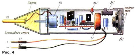
The transformer is wound on a K20x10x5 ring made of 2000NN ferrite and contains 250 turns of PEV-2 0,2 wire with a tap from the 230th turn, counting from the left according to the output scheme. Most of the parts are mounted on a printed circuit board (Fig. 3) with dimensions of 20x70 mm, which is fixed inside a cylindrical body (Fig. 4). When mounting the microcircuit, its free terminals 1,2,8 should be connected to a common wire. The dynamic head is glued to the end cap, which has holes drilled into it. A variable resistor is installed on the side of the X3 probe, its axis enters the conical tip and is fixed in it with epoxy resin. By turning the tip relative to the body, the required level of the output signal of the probe or the sensitivity of the amplifier is set.
Of course, another case is also suitable, for example, a rectangular one, in which you can install a conventional dynamic head. Then the probe is made remote and connected to the parts of the probe with a shielded wire (the screen is soldered to the power minus). When adjusting the probe, by selecting the resistor R5, the generator frequency is set to approximately equal to 1000 Hz, and by selecting the resistor R7, such an operation mode of the VT3 transistor is achieved in which the generator signal supplied to the HZ probe is not distorted even with the upper position of the variable resistor engine according to the circuit. Literature
Author: I.Potachin, Fokino, Bryansk region
Artificial leather for touch emulation
15.04.2024 Petgugu Global cat litter
15.04.2024 The attractiveness of caring men
14.04.2024
▪ Used medical masks for road construction ▪ Bacteria that can eat plastic ▪ Intel Cyclone 10 Field Programmable Gate Arrays ▪ Robot for the evacuation of the wounded
▪ site section Acoustic systems. Article selection ▪ article by Martin Heidegger. Famous aphorisms ▪ article Are there flowers that are fragrant at night? Detailed answer ▪ article Work in forest nurseries. Standard instruction on labor protection ▪ article Electronic power switch-fuse. Encyclopedia of radio electronics and electrical engineering
Comments on the article: Sergey, Sergey852@gmail.com I am currently doing my thesis on this article. Who needs it, please contact)
Home page | Library | Articles | Website map | Site Reviews
www.diagram.com.ua |


 Leave your comment on this article: