|
|
ENCYCLOPEDIA OF RADIO ELECTRONICS AND ELECTRICAL ENGINEERING Packet communication: AX.25 protocol. Encyclopedia of radio electronics and electrical engineering
Encyclopedia of radio electronics and electrical engineering / Data transfer In the implementation of packet communication on amateur radio between two or more correspondents, the exchange of information is carried out in accordance with some established procedure, which is called the exchange protocol. In this case, the AX.25 protocol is used, which is a revised version of the X.25 protocol specifically for amateur radio purposes. Exchange protocols contain seven levels. The entire logic of the radio channel operation procedure is described in the second level. In practice, it is implemented, as a rule, by a special packet communication controller (TNC), which is placed between the computer and the transceiver. The AX.25 exchange protocol provides multiple (multiple) access to the communication channel with occupancy control. All stations are considered equal. The TNC of the station checks whether the channel is free or not before starting up. If it is busy, then the channel is checked until it is free, and only after that the station is switched on for transmission. In packet communication, messages are transmitted in blocks - frames. In addition to information, the frame contains data on the purpose of the frame, the addresses of the sender, recipient and relay through which the message must pass, as well as a checksum that allows you to check the correctness of the received frames. Frame format. Each completed piece of information is a frame. It has a specific format. Each frame starts with a unique bit sequence 01111110, which is called a flag and allows you to recognize the beginning of the frame. Next come the address field ranging in size from 14 to 70 bytes, control - one byte, information - from 0 to 256 bytes, control - 2 bytes. When using the network, the third level of the protocol, an additional identification field is formed, which acts as part of the information field. The frame also ends with a flag.
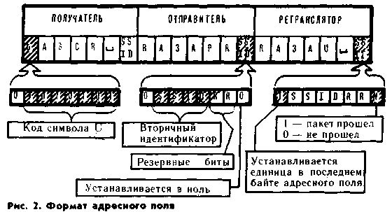
flag field. As already noted, the flag field is a unique bit sequence 01111110. If the same sequence occurs later in the frame, then in order for the correspondent not to take it as a sign of the end of the packet, a zero is inserted after the fifth bit. Address field (Fig. 2). It can contain from two to ten amateur radio call signs. The simplest case is two callsigns, if two correspondents work directly with each other. If these correspondents are out of radio visibility, then they can use the stations of other operators as a repeater. There can be up to eight of them in one line. Repeater call signs are also included in the address
field. Thus, it is divided into three subfields: recipient, sender, and relay. Callsigns entered in it can consist of no more than six characters. If the call sign is less than six characters long, it is padded with the appropriate number of spaces. After the callsign in each subfield comes a secondary station identifier. This is a number from 0 to 15. It means that the operator has several packet communication stations, BBS equipment, and NET / ROM. Usually the operator himself works with a call sign without a number or with number one, the numbers from 2 to 9 are additionally added to the call sign of the "mailbox" and the hub station, and when the signal passes through NET / ROM from 10 to 15, depending on whether through how many node stations the packet passed. The number of the identifier in binary form takes four bits - from the second to the fifth in the byte following each callsign. On fig. 2, these bits are designated as SSID (SECONDARY STATION IDENTIFIER). The first bit of this byte is used as a sign of the end of the address field. If it is designated by one, then this is a sign of the last byte of the address field. There is no specific purpose for the sixth and seventh bits, and they can be used in local networks by agreement of users. The eighth bit in the sender and recipient subfield is set to zero. In the relay subfield, it is denoted by one if the packet passed through the relay, and zero if not.
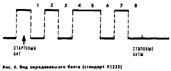
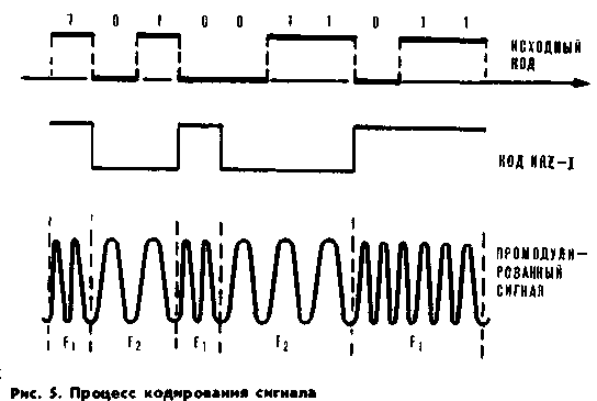
The setting of the repeater bit is necessary so that the repeaters located in the radio visibility zone of each other follow the order of transmitting packets through themselves and perform this procedure strictly in the order specified by the sender of the packet. control field. It contains frame type information that is used to determine the destination of the message. All packet frames can be divided into three main types: I - information frames containing symbolic or digital information; S - service, confirming that the frame is received, or containing a request for the issuance of the next information frame; U - unnumbered frames - connection-disconnect request. Beacon signals also belong to this type. In addition, this field contains the number of the frame being sent or, in case of confirmation of receipt of the message, the number of the next frame that the correspondent's TNC is ready to receive. Such a numbering was introduced because several frames can be transmitted through the channel in a row - from one to seven, and it can help to sort out in case of failures. If an error occurs in any of the frames, then the receiver controller will inform the sender controller that it is ready to receive the frame number that has not yet been received or was received with an error. For example, if one station sent four packets to another in a row and an error occurred when receiving the third packet, then the recipient's controller, translated from machine language into human language, will inform the sender: "ready to receive the third packet." Information field. It contains useful information of up to 256 bytes, presented in codes and which, when received by correspondents, is displayed on the computer display screen of amateur stations. Sometimes the first bit of the information field acts as an independent subfield - the protocol identifier. This happens when using the third, network layer, when the packet passes through NET / ROM. The control field serves to check the correctness of the radio exchange. It is a sixteen-digit number that is calculated using the polynomial XI6 + + XI5 + X2 + 1 in accordance with the algorithm given in the recommendations of ISO 3309 (HDLC) - International Orqa-nization Standardization, Hiqht - Level Data Link Control Procedures. The sender's TNC calculates the no checksum for the entire frame and places it at the end of the frame. At the receiving end, according to the same algorithm, it is calculated again and checked against the sum placed at the end of the frame. If these two numbers match, then the frame is considered to be received correctly. There are several ways to calculate the checksum: hardware and software. With the hardware method, the frame passes through a certain device (adder), and as a result, a certain number is written in its register, which is the checksum. The second way is to count using a special program. In this case, the frame is first received into the RAM by the polyst, and then the count is made. The first method implements high performance, but requires additional hardware. The second method has a lower performance, but does not require additional hardware costs. Recall how the structure of a packet communication station should look in order to implement the AX.25 protocol. It can be seen from the diagram (Fig. 3) that the station includes a computer, a TNC, a transceiver, and an antenna-feeder device. The computer can be used by almost anyone. When conducting experiments on packet communication during the Soviet-Canadian skiing, the following PCs were tested: "Robotron 1715", "Radio-86RK" and BK-0010. Abroad, the most popular computers used in the packet communication system are IBM PC, COMMODORE 64, TANDY, APPLE, for which powerful software has been developed that opens up wide possibilities for using packet communication. One indispensable condition when choosing a computer for packet communication is the presence in it of a serial exchange channel operating according to the C2 interface standard (RS232). As you know, Radio-86RK does not have such a channel, so RA3AU has developed a special program "Terminal" that imitates this channel. When working at a packet communication station, the operator types information on the keyboard, and receives answers in the form of symbols on the monitor screen. The information transmitted by the operator can either be a command to the TNC or text intended for the correspondent. When a key is pressed, the computer determines the code corresponding to that key and sends it over the serial link. The exchange on this channel occurs byte by byte. The type of transmitted byte is shown in fig. 4. Some parameters that characterize the transmitted byte may be different, but it is necessary that the parameters set in the TNC and in the computer match. They are characterized by the following parameters; information word length (7 or 8 bits), odd or even parity, start bit (one), table bit (one, one and a half or two), baud rate (50, 75, 150, 300, 1200, 2400, 4800 or 9600 bps). Voltage levels used in this interface: one - from +3 to +12 V, zero - from -3 to -12 V. Information in the direction from the computer is transmitted via the TXD line, and in the opposite direction via the RXD line, in addition, there are two more additional lines CTS and RTS, through which a signal is given that the computer or TNC is ready to receive the next byte. Before sending a byte on the TXD line, the computer checks the CTS line. If the signal level on it characterizes the readiness of the TNC to receive a byte, then the computer sends it, if not, it expects a change in level. A similar procedure is performed by the TNC using the RXD line to transmit an information byte and the RTS line to check for readiness. The sequence of several bytes received by the TNC can be either a command or information intended to be sent over the air. In the first case, the command is decoded and executed, in the second, a frame is formed in accordance with the AX.25 protocol and transferred from the standard code to the NRZ-1 code (non return to zeroinverted). This standard stipulates that the transition of the physical level of the signal occurs if 0 occurs in the sequence of transmitted bits. A timing diagram explaining this process is shown in fig. 5, which shows the original package - and it is also in the form of the NRZ-1 code. Typically, the modem is structurally made in the same package as the TNC. Its digital part, as a rule, is called the assembler-disassembler of frames. The frame assembler-disassembler and the modem are interconnected by four lines: TXD - for transmitting frames in the NRZ-1 code, RXD - receiving frames in the NRZ-1 code, PTT - to turn on the modulator and DCD, through which a signal from the demodulator about the channel is busy . A modem is a collection of two devices: a modulator and a demodulator. Before sending the packet, the frame assembler-disassembler turns on the modem using a signal on the PTT line and sends a frame in the NRZ-1 code via the TXD line. The modulator fills the received sequence with two sound frequencies. One corresponds to the F1 frequency, and zero corresponds to the F2 frequency. The signal, modulated by the sound frequency, is fed through the MlC line to the microphone input of the transmitter. When frames are received, a sequence of pulses filled with audio frequency is fed from the output of the transceiver via the EAR line to the input of the demodulator. The demodulator performs the reverse process: it extracts an envelope from a sequence of audio frequency pulses, which is a frame in the form of an NRZ-1 code. This frame enters the package assembler-disassembler. Simultaneously with the appearance in the channel of a signal modulated by one of the frequencies F1 or F2, a special detector is activated, generating a signal at the output indicating that the channel is busy. The PTT signal, in addition to turning on the modulator, performs another function - it controls a transistor switch that switches the transceiver from reception to transmission. There are two types of modems used in amateur radio packet communication: for short and ultra-short waves. On KB, single-sideband modulation is used, and the transmission rate over the radio channel is 300 bit / s, while the spacing of audio frequencies corresponding to zero and one should be 200 Hz. The modulation frequency can be different. However, the convenience of reading the operating frequency of a radio station in Europe has adopted a standard according to which it is established that zero corresponds to 1850 Hz, and one corresponds to 1650 Hz. On ultrashort waves, they operate at a transmission rate of 1200 bit / s with a frequency separation of 1000 Hz. Since, as a rule, frequency modulation is used on VHF, the frequencies must be strictly fixed. It is accepted that zero corresponds to 1200, and unit - 2200 Hz. In conclusion, I would like to inform you that the draft of the new instructions for the operation of amateur radio stations, developed by the USSR Federal Reserve System, which is undergoing the approval stage, includes amateur packet communication as an equal in rights. Author: E. Labutin (RA3APR); Publication: N. Bolshakov, rf.atnn.ru
Artificial leather for touch emulation
15.04.2024 Petgugu Global cat litter
15.04.2024 The attractiveness of caring men
14.04.2024
▪ Smartphone Honor Play4 Pro with thermometer function ▪ ASUS ROG Ally Portable Game Console ▪ Found the closest black hole to us ▪ Women's brains age more slowly ▪ MPC17C724 - motor driver chip
▪ site section Power regulators, thermometers, heat stabilizers. Article selection ▪ article saber rattling. Popular expression ▪ article How do our kidneys work? Detailed answer ▪ article Operation of dryers in hairdressing salons. Standard instruction on labor protection ▪ article Flashing red light. Encyclopedia of radio electronics and electrical engineering
Home page | Library | Articles | Website map | Site Reviews www.diagram.com.ua |


 Arabic
 Bengali
 Chinese
 English
 French
 German
 Hebrew
 Hindi
Hindi Italian
 Japanese
 Korean
 Malay
Malay Polish
 Portuguese
 Spanish
 Turkish
 Ukrainian
 Vietnamese


 Leave your comment on this article: