|
|


 Arabic
 Bengali
 Chinese
 English
 French
 German
 Hebrew
 Hindi
Hindi Italian
 Japanese
 Korean
 Malay
Malay Polish
 Portuguese
 Spanish
 Turkish
 Ukrainian
 Vietnamese
|
ENCYCLOPEDIA OF RADIO ELECTRONICS AND ELECTRICAL ENGINEERING Wiper switch. Encyclopedia of radio electronics and electrical engineering
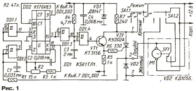
Encyclopedia of radio electronics and electrical engineering / Automobile. Electronic devices On cars of early years of production, as is known, there is no provision for smooth regulation of the duration of pauses between the working strokes of the windshield wiper blades in intermittent mode, and on some cars, instead of intermittent mode, the slow stroke mode of the wipers is used. Therefore, if the windshield wiper switch on your car has failed or the existing one is no longer satisfactory for you, we recommend assembling a more advanced device described in this article. Radio amateurs pay quite a lot of attention to the design and operation of a car windshield wiper - the magazine has published about a dozen completed devices alone over the last twenty years (for example, [1-7]). As practice has shown, the most stable time characteristics of the brush movement cycle were provided by those assembled on digital microcircuits. Based on the results of the analysis of published switches, a design assembled on digital microcircuits was developed and tested in operation, in which it is possible to abandon the oxide timing capacitor. The switch is designed for installation in VAZ-2103, VAZ-2106 cars instead of the windshield wiper relay, but can also be used on other models of the VAZ series. In a slightly modified form, the switch is suitable for GAZ-24 and Moskvich-2140 cars. The device diagram is shown in Fig. 1. It consists of a generator of time intervals with adjustable duration, assembled on the counter-generator DD2, a generator of a group of working cycles of the brushes when the windshield wiper is first turned on on element DD1.4, capacitor C3 and resistor R4. The drive motor M1 is turned on by the thyristor VS1, controlled by the current amplifier on the transistor VT1.
The switch is connected to the vehicle's electrical system in accordance with the specified color designation of the wires. The windshield wiper relay in the car is removed. In the initial position of the wiper mode switch, power is not supplied to the switch. When the switch is moved to position "I", wire 1 will receive on-board voltage, and wire 3 will be connected to the body. Since at the moment of switching on, the voltage at the top terminal of capacitor C3 in the circuit is close to zero, a high level voltage will flow from the output of the Schmitt trigger DD1.4 to the base of the transistor VT1, which will open the transistor VT1, and it, in turn, will open the thyristor VS1. The windshield wiper motor will receive power and begin to operate. At the same time, through the smoothing circuit R1C1 and the Schmitt triggers DD1.1 and DD1.2, which act as buffer elements, a high level voltage from the electric motor will be supplied to the zeroing input of one of the counters of the DD2 microcircuit and will keep the counters in the zero state (low level at output 15). Each time the moving contact of the limit switch SF1 of the windshield wiper drive is switched to the right position according to the diagram, the thyristor VS1 will close, and when returning to its previous position, it will open again until the capacitor C3 is charged through the resistor R4 to the threshold switching voltage of the trigger DD1.4. This will happen after 5...7 s, during which the brushes will make several continuous strokes. After switching trigger DD1.4, a low level will appear at its output, since the output of element DD1.3 is high. Transistor VT1 will close, and the next time the moving contact of the limit switch returns, SCR VS1 will remain closed, and the wipers will stop operating in continuous mode. When the engine stops, a low level will appear at the R input of the DD2 microcircuit and the counters will begin counting the pulses generated by the generator section of this microcircuit. The generation frequency can be adjusted with variable resistor R2. When the number of pulses counted by the counter reaches 214, a high level will appear at output 15 of the counter. A low level from the output of the inverter DD1.3 will switch the trigger DD1.4 to the single state. Transistor VT1 will open and turn on thyristor VS1 - the electric motor will start working. As soon as the moving contact of the limit switch moves to the right position, the thyristor VS1 will close, and a high level will again appear at the R input of the counter of the DD2 microcircuit, which will reset the counters. The windshield wiper blades will complete one cycle and stop. Then counter DD2 will start counting pulses again and the process will repeat. The wiper will operate intermittently. By changing the resistance of the variable resistor R2 from zero to maximum, you can change the pause time between the working strokes of the brushes from 0,5 to 20...25 s. The use of the K176IE5 microcircuit in the switch made it possible to use a small capacitance capacitor C2 to set time intervals, which increased the reliability and stability of the device. Diode VD2 suppresses voltage pulses of reverse polarity in circuit R1C1. In addition, it increases the noise immunity of the thyristor (without a diode, when the moving contact of the limit switch SF1 was returned, the thyristor opened again). Since the voltage in the vehicle’s on-board network can sometimes (during malfunctions) exceed 15 V, a zener diode VD1 with a ballast resistor R7 is introduced for protection. The K561TL1 chip in the switch can be replaced with the imported IW4093BN or K561LA7, K564TL1, K564LA7 (the use of Schmitt triggers is preferable). Transistor - any low-power silicon, npn structure. The thyristor is suitable for any of the KU201, KU202 series. Zener diode - for stabilization voltage 10...12 V; In addition to what is indicated in the diagram, D814V, D814D, KS512A, KS213B, KS212E are suitable. Diode VD2 - any of the KD105, KD208, KD209, KD223, KD226 series. Capacitors should be selected from the K73-9, K73-5, K73-11, etc. series. Capacitor C3 should have a low leakage current, so it is better not to use an oxide one. Variable resistor R2 can be anything, with a resistance from 22 to 100 kOhm; it is required only to maintain the limits for adjusting the pause duration so that the product C2 (R2+R3) remains close to 18x48x10 s. It is advisable to select resistor R2 (47 kOhm) from group B or C so that the tuning scale is close to linear. When installing the switch on GAZ-24 or M-2140 cars, it is necessary to make small changes to it, since the connection diagram for the windshield wiper motor in these cars differs from the VAZ one (Fig. 2).
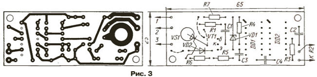
As can be seen from the figure, the thyristor VS1 and the diode VD2 must be swapped, the trigger DD1.1 remains free. The signal from the output of inverter DD1.2 goes directly to the R input of the counter. The required changes in the vehicle's electrical circuit are shown in a fragment of the circuit. The cross marks the conductor that needs to be removed ("broken"). When switched on in this way, in position “1” of the SA1 “Mode” switch, instead of a quiet operation, there will be intermittent operation with smooth adjustment of the pause time. In positions “2” and “3” the switch is de-energized, the windshield wiper operates in the mode set by the factory. All parts of the device, except for the variable resistor R2, are placed on a printed circuit board made of foil fiberglass 1,5 mm thick. The board drawing is shown in Fig. 3. The topology of the conductors on the board is designed so that both versions of the switch can be assembled on it. Corresponding changes in the board installation are made by installing jumpers made of flexible insulated wire and cutting the printed conductors.
The board is mounted near the variable resistor R2, the handle of which is located on the instrument panel in a convenient place. The switch does not require setup. If you need to change the time of continuous operation of the brushes when first turned on, select resistor R4. The pause time control limits can be changed by selecting capacitor C2. Literature
Author: I.Potachin, Fokino, Bryansk region
Artificial leather for touch emulation
15.04.2024 Petgugu Global cat litter
15.04.2024 The attractiveness of caring men
14.04.2024
▪ Ecological medicines from waste paper industry ▪ Bilingualism improves brain health and mental health ▪ Audi, GM, Honda and Hyundai are moving to Android ▪ Wheat breeding has led to a decrease in its resistance
▪ section of the website Electrotechnical materials. Article selection ▪ The road to hell is paved with good intentions. Popular expression ▪ article Which language contains only 12 letters? Detailed answer ▪ article Therapist for teenagers. Job description ▪ article Talking coin. Focus Secret
Home page | Library | Articles | Website map | Site Reviews
www.diagram.com.ua |


 Leave your comment on this article: