|
|
ENCYCLOPEDIA OF RADIO ELECTRONICS AND ELECTRICAL ENGINEERING Practical designs of DJ9BV antennas for the 144 MHz band. Encyclopedia of radio electronics and electrical engineering
Encyclopedia of radio electronics and electrical engineering / VHF antennas The purpose of the article published below is a brief analysis of the current state of antenna-feeder technology and a description of the practical design of a simple, efficient and technological antenna developed by the famous German ultrashortwave Ponter Hoch (DL6WU), which was modified and brought to high manufacturability by Rainer Bertelmeyer (DJ9BV), who has been for many years the "legislator" of European novelties in terms of VHF technology [1,2]. Among the variety of VHF antennas used for amateur radio communications [3, 4], a special place is occupied by "wave channels" with an elongated traverse (boom), as the easiest to manufacture, non-critical to tuning, allowing you to get a large gain and a decent radiation pattern. In addition, they can be used to create a complex highly efficient antenna-feeder system for conducting radio communications across the Moon. In table. 1 shows the main characteristics of the most common "wave channels" for the two-meter range. As can be seen from it, there is a tendency to improve the parameters of the antenna with an increase in the length of the traverse. A significant difference in relation to F / B (forward / backward") is caused by the use of complex reflectors in some cases. Table 1
All "wave channels" on the VHF bands can be conditionally divided into three types according to the way the elements are arranged on the traverse: they can be electrically connected to a metal boom, isolated from it, or located on a non-metallic boom. Each type has its own "boom effect" - the degree of influence of the diameter of the boom on the electrical length of the element passing through it. The required geometric length of the element depends not only on the diameter of the boom, but also on the diameter of the element itself. After the publication by K. Fechtel of the description of the antennas "TONNA" (F9FT) in the journal "Radio" [5], many ultrashortwaves of the former USSR repeated these designs, which for a long time became a kind of standard for VHF antennas. Along with the ease of manufacture, these designs have a number of significant fundamental drawbacks. First, the lack of matching and balancing casts doubt on the possibility of obtaining a "pure" radiation pattern. Secondly, the elements located on the boom are electrically connected to the latter. Any mechanical connection does not guarantee long-term reliable electrical contact of heterogeneous metals (even aluminum - duralumin). The absence of element-boom contact or its unstable nature leads to a change in the antenna parameters (increase in SWR, diagram distortion, noise). Thirdly, if there are no boom materials at hand and elements that fully correspond to the description, then the use of random materials does not allow you to get the expected results. The proposed design of the DJ9BV antenna is free from these shortcomings. In table. 2 shows the main geometric dimensions of this antenna, in it R denotes a reflector, DE is a vibrator, D is a director. Table 2
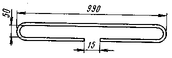
Antennas 2,2l, 3,6l, 4,0l, 4,4l long have a single reflector, 1,8l, 3,2l, 4,8l long have a double reflector that increases the forward / backward radiation ratio. The boom is made of a duralumin square section with dimensions of 20x20x2 mm. The elements are made of 4 mm duralumin rod. The vibrator is made of an aluminum tube with an outer diameter of 8 mm and a wall thickness of 1 mm. The design of the active vibrator is shown in fig. 1. The middle point of the vibrator can be electrically connected to the boom.
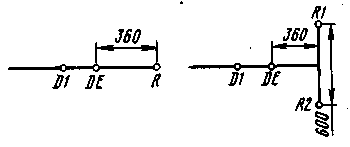
The matching U-elbow is made from a length of 680 mm coaxial cable with a characteristic impedance of 50 ohms. Particular attention should be paid to the reliability of the waterproofing of the junction of the vibrator with the U-elbow and the feeder. The design of a vibrator with a resistance of 300 Ohm is described in [6]. The placement of reflectors is shown in Fig.2.
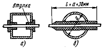
With a boom diameter of more than 20 mm, the length of all passive elements must be increased by 1 mm at a diameter of 25 mm, by 3 mm at 30 mm, by 6 mm at 40 mm. Subject to adjustments for the length of each element, the boom can be made from pipes of various diameters. The use of a telescopic boom increases the mechanical strength of the structure. If the diameter of the passive elements is 5 mm, the lengths of all elements must be reduced by 4 mm. Passive elements must be reliably isolated from the carrier beam. Options for placing elements are shown in Fig.3.
Figure 3a shows the DJ9BV variant, in fig. 3b - RW3TJ. In the first case, standard nylon bushings with a 4 mm diameter hole were used. In the second, 5-mm elements and pieces of tubes made of stabilized polyethylene are used (sheath of the PK75-4-12 coaxial cable). The electrical parameters of various antenna options at a frequency of 144,5 MHz with an SWR of at least 1,2 are given in Table. 3. Table 3
The columns "Distance E" and "Distance H" indicate the optimal distances between antennas in the vertical and horizontal planes in the manufacture of antenna arrays. Dimensions can be changed within the range from 80 to 105% of those indicated in the table. Reducing the size allows you to improve the radiation pattern, and increasing - to increase the gain. The four antennas DJ9-2-4,0 gives a gain increase of +5,9 dB in relation to a single one, the total gain of such an antenna is 20 dB. The author of the article made and tested four designs of DJ9BV antennas. DJ9-2-3.6 antennas have been operated for a long time at the UZ3TXB radio station, were used in the UW3TJ / A and RU1R expeditions. The DJ9-2-4,4 antenna showed excellent results in the UA1C expedition, allowing the VHF team of the RRR Committee to show the best result in the "VSS-93" contest. The author expresses his deep gratitude to DJ9BV for the kind permission to use the results of his work [2] and expresses confidence that this publication will enable ultrashortwave workers to manufacture highly efficient antennas and antenna systems. Literature 1. Gunter Hoch (DL6WU). Extreme lange Yagi-Anicnnen. - UKW-BERtCHTE. 1992, No. 1.
Author: Oleg Arkhipov (RW3TJ), Nizhny Novgorod; Publication: N. Bolshakov, rf.atnn.ru
A New Way to Control and Manipulate Optical Signals
05.05.2024 Primium Seneca keyboard
05.05.2024 The world's tallest astronomical observatory opened
04.05.2024
▪ Latex Printing Technology on Rigid Media ▪ Lavo home hydrogen batteries ▪ The chances of meeting aliens are almost zero ▪ Single-chip systems Qualcomm IPQ8074 and QCA6290 ▪ LMX9838 - Bluetooth module with serial port profile
▪ section of the site Alternative energy sources. Article selection ▪ article Coachman, don't drive the horses! Popular expression ▪ article What is the pleasure center and where is it located in the body? Detailed answer ▪ Merchandiser article. Standard instruction on labor protection ▪ article Miracle album. Focus Secret
Comments on the article: Sergei A very useful site for antenna builders, both for beginners and experienced radio amateurs. Thanks a lot!
Home page | Library | Articles | Website map | Site Reviews www.diagram.com.ua | ||||||||||||||||||||||||||||||||||||||||||||||||||||||||||||||||||||||||||||||||||||||||||||||||||||||||||||||||||||||||||||||||||||||||||||||||||||||||||||||||||||||||||||||||||||||||||||||||||||||||||||||||||||||||||||||||||||||||||||||||||||||||||||||||||||||||||||


 Arabic
 Bengali
 Chinese
 English
 French
 German
 Hebrew
 Hindi
Hindi Italian
 Japanese
 Korean
 Malay
Malay Polish
 Portuguese
 Spanish
 Turkish
 Ukrainian
 Vietnamese


 Leave your comment on this article: