|
|


 Arabic
 Bengali
 Chinese
 English
 French
 German
 Hebrew
 Hindi
Hindi Italian
 Japanese
 Korean
 Malay
Malay Polish
 Portuguese
 Spanish
 Turkish
 Ukrainian
 Vietnamese
|
ENCYCLOPEDIA OF RADIO ELECTRONICS AND ELECTRICAL ENGINEERING Low power chargers. Encyclopedia of radio electronics and electrical engineering
Encyclopedia of radio electronics and electrical engineering / Automobile. Batteries, chargers Along with traditional chargers that provide a nominal battery charging current (up to 10 A), motorists widely use home-made low-power, and therefore small-sized and lightweight devices focused on solving private problems. Below are descriptions of two such structures. One of them is designed for a charging current of up to 1,5 A. The author suggests installing it permanently on a car and connecting it to the battery terminals. The second - for a charging current of about 0,5 A - is designed to service the battery during long interruptions in operation. The described low-power mains charger is used to charge a car battery with a small current. Structurally, it is designed for installation in a vehicle with connection to the electrical system. Thus, it is not necessary to deploy the charger and connect it to the battery every time, just insert the plug into the socket. This makes it possible to charge the car battery wherever there is access to a 220 V power supply. In parallel with charging, the device allows the use of a car radio. The charger circuit is shown in fig. one.
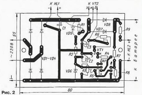
Op-amp DA1 controls the voltage at the output of the device and, when the output voltage set by resistor R3, limits the current through the battery at the level of its self-discharge current. Capacitor C1 is designed to smooth out ripples. At a current of 1,5 A, the ripple voltage is approximately 5 V. The VD6 zener diode stabilizes the supply voltage of the op-amp. Resistor R6 serves to limit the charging current. From the voltage divider, assembled on resistors R7 and R8, a voltage proportional to the output is supplied to the inverting input of the op-amp. LED HL1 serves to indicate the presence of voltage in the network, and HL2 - to indicate the connection to the battery. Thanks to the resistor R6, the charging current does not depend much on the voltage on the battery, but when the set output voltage is reached, the charging current decreases to the value of its self-discharge current. In this mode, the device can work for an unlimited time, so there is no need to control the charging process. The device is also not very sensitive to an emergency circuit of the output circuit, but a long stay in this mode is undesirable. To protect the operator from electric shock, a three-wire cable with double insulation and an X1 Euro plug is used at the end. Of course, the protective contact of the reciprocal euro socket must be reliably grounded. If the mains phase accidentally hits the car body (due to damage to the mains cable), one of the fuses blows, the device is de-energized. The secondary winding of the network transformer T1, in any case, must be reliably isolated from the primary and from the magnetic circuit. It must be remembered that when charging the battery in a random place where the euro-socket may be ungrounded, you expose yourself to real danger, so do not neglect any protective measures (rubber mat or dry board under your feet, rubber gloves or dry fabric mittens). The charger is structurally designed in a plastic box from the Berdsk electric razor. I placed the box under the hood of my VAZ 21063 car. attached to the interior partition of the machine next to the place for spare parts. Transformer T1 - any small-sized network power of 25 W with a secondary winding for a voltage of 15.5 ... 17.5 V at a current of 1.5 A. Diodes VD1-VD4. VD7, VD8 any of the KD226 series will do; it is possible to replace them with KD212 KD213 and others of medium power. Diode VD5 - KD522. KD521 with any letter index or other small-sized ones. Instead of KS191Zh, a zener diode KS 191E is suitable. Green LED AL307V can be replaced with AL307G. AL307GM. AL307NM. and AL307B of red glow - on AL307K. AL307BM. AL307KM. OU K140UD1208 will be replaced by K140UD1408. while the resistor R5 is excluded, and pin 8 is left free. The KT825G transistor is mounted on a heat sink plate with an area of 60 cm2 and a thickness of 3 mm. Fixed MLT resistors, trimming resistors - SPZ-38B. SPZ-19 or other small-sized ones. Capacitors - K50-35, K50-24 or K50-16. Most parts of the device are mounted on a 1.5 mm thick foil fiberglass printed circuit board. The drawing of the board is shown in fig. 2.
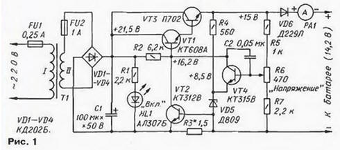
When manufacturing a device for installation on a car, special attention should be paid to the rigidity of mounting massive parts on the board and other components and parts in the box, as well as to protecting the device from moisture and dust. To establish the device, a DC voltmeter is connected to its output instead of a load and the voltage is set within 3 ... 13.4 V by resistor R13.6. Then a discharged battery is connected to the output of the device in series with an ammeter and the required charging current is set by resistor R6 within 0.5 ... 1.5 A. Author: A.Korsakov, Orel As you know, car batteries during a long period of storage, such as winter storage, are discharged, so they are recommended to be recharged periodically. The described device is designed to automatically maintain a car battery in a charged state during storage. Its functionality, compared with the set of equipment described by the author of these lines in the article "Attachment-automatic to the charger" ("Radio", 1997. No. 7. pp. 44-46), is more modest, but it is much simpler and does not contain electromechanical relays. The schematic diagram of the device is shown in fig. 1.
Transistors VT1, VT3, VT4 and a zener diode VD5 form a series voltage regulator. The voltage that the device maintains on the battery is set by resistor R6. The limits of this voltage change are determined by the resistance of resistors R5 and R7. The charging current is controlled on the scale of the ammeter RA1. When you connect the device to the battery, the voltage on it is usually less than the charging one. Therefore, the regulating transistor VT3 is open and saturated, the maximum current flows through it. To protect the control transistor from overload, a current limiter is assembled on the transistor VT2. With increasing load current, the voltage drop across the current-measuring resistor R3 increases, and at some point the transistor VT2 opens slightly, reducing the base current of the composite regulating transistor VT1, VT3. As a result, the charging voltage, and hence the current through the transistor VT3, decrease. Thus, the maximum possible current through the stabilizer - the charging current of the battery - depends on the resistance of the resistor R3. As the battery charges, the voltage on it increases, approaching the stabilization voltage, and the charging current decreases to a value necessary only to compensate for its self-discharge. Diode VD6 is used to protect the battery from discharging through the stabilizer circuit in the event of a power outage. A smoothing capacitor C1 is connected behind the charger rectifier. It is not needed to reduce the level of ripples during charging, since, firstly, with the capacity indicated on the diagram, its smoothing effect will be noticeable only at an extremely low charging current and. secondly, it is not required to smooth the charging current at all. This capacitor allows you to adjust the output voltage of the device - with it there is no ripple at low load. The inclusion of the device in the network is signaled by the LED HL1. The device is designed for long-term operation under voltage without constant supervision, therefore, to increase the reliability, its parts are selected with a margin for the main parameters. Transformer T1 is suitable for anyone with a power of 20 ... 25 watts. with good interwinding insulation, providing a voltage of 17 ... 19V on the secondary winding at a current of 0.5 A. Fixed resistors, except R3. - MLT; variable resistor R6 - PPP-1Z. Resistor R3 - wire, homemade (Fig. 2). It is wound with nichrome wire 3 with a diameter of 0,3 mm on a fiberglass strip 2 with a thickness of 1 mm. Since nichrome is poorly soldered, the connection of the wire with copper terminals 1 is made with screws 4 with M3 nuts.
Ammeter RA1 - any with a total deviation current of 0.5 ... 0.6 A. Transistor VT3 and diode VD6 are installed on heat sinks with an area of at least 100 and 10 cm2, respectively. The device is mounted in a robust housing with dimensions of 170x120x90 mm. Ammeter RA1 is displayed on the front panel. mains voltage indicator HL1. fuse holders FU1 and FU2 and resistor knob R6. Ventilation holes must be drilled in the casing. Most of the small parts are mounted on a printed circuit board made of fiberglass with a thickness of 1 mm. The board drawing is shown in fig. 3. In the drawing, the areas where the foil was removed with a cutter are blackened.
The P702 transistor can be replaced with KT802A, KT805A or KT819 with any letter index; KT608A - on KT801A or KT8 15A; KT315V - on KT315B or KT315G; KTZ12V - on KT312B. Instead of D809, zener diodes D808, D810, D814A - D814V are suitable. Establishing the device begins with checking the limits of voltage regulation by resistor R6. To do this, a temporary load resistor with a resistance of 300 ohms and a power of 1 W is connected to the output. In the extreme positions of the engine of the resistor R6, the voltage at the emitter of the transistor VT3 should be equal to 13.8 and 16.8 V. If necessary, these limits are adjusted by selecting resistors R5, R7. The scale under the handle of the resistor R6 is calibrated from 13 to 16 V using a standard voltmeter connected in parallel with the load. By selecting the length of the wire of the resistor R3, the limiting current through the stabilizer is set at a level of about 0,5 A. A typical dependence of the output voltage of the stabilizer on the load current is shown in fig. 4.
For charging, the battery is connected to the device in the appropriate polarity, the voltage is set by the resistor R6, which the charged battery should have in accordance with its operating instructions, and the device is connected to the network. When designing a device, care should be taken to ensure reliable insulation of current-carrying parts electrically connected to the network. Nevertheless, when operating the device, especially in a garage, you should take all precautions so as not to get electrocuted. Author: I. Herzen, Berezniki, Perm region
Artificial leather for touch emulation
15.04.2024 Petgugu Global cat litter
15.04.2024 The attractiveness of caring men
14.04.2024
▪ Poisonous insects prefer medicinal plants ▪ Electronics will evaluate the level of sweetness of food and drinks ▪ Apple creates 3D interface for iPhone and iPad
▪ section of the site Grounding and grounding. Selection of articles ▪ article by Peter Kapitsa. Biography of a scientist ▪ article What is electric eel? Detailed answer
Comments on the article: Eugene I assembled the circuit according to Fig. 1. The current is dead within 0,6 amperes and is not regulated in any way. Is there an error in the diagram?
Home page | Library | Articles | Website map | Site Reviews
www.diagram.com.ua |


 Leave your comment on this article: