|
|


 Arabic
 Bengali
 Chinese
 English
 French
 German
 Hebrew
 Hindi
Hindi Italian
 Japanese
 Korean
 Malay
Malay Polish
 Portuguese
 Spanish
 Turkish
 Ukrainian
 Vietnamese
|
ENCYCLOPEDIA OF RADIO ELECTRONICS AND ELECTRICAL ENGINEERING Relay-regulator with temperature compensation. Encyclopedia of radio electronics and electrical engineering
Encyclopedia of radio electronics and electrical engineering / Automobile. Electronic devices The article considers an automotive relay-regulator based on the PIC12F675 microcontroller, which is built into the regular regulator housing. Its main feature is maintaining the optimum voltage at the battery terminals with the engine running, depending on its temperature. In magazines and the Internet, quite a lot has been said about the "life" of automotive batteries (batteries) and there are many different chargers, from simple to complex, restoring the "life" of the battery. Great interest is due to the fact that automotive voltage regulators often do not provide optimal battery recharging, especially in winter. In addition, chargers are designed for preventive charging outside the car, which is not very convenient. As you know, the voltage of a lead battery depends on its temperature. The lower the temperature, the lower the rate of chemical reactions and the more voltage must be applied to the battery when charging. Regular relay-regulators are often built on simple comparator circuits and are unable to provide proper charging. There are also temperature-compensated regulators on sale, but they are installed inside the generator, and after heating up from the engine, they are also unable to properly monitor the temperature of the battery. There are also three-level regulators, but they require, although rare, manual switching of the voltage mode (for example, "minimum", "normal", "maximum") in accordance with the temperature outside the car. The proposed device replaces the standard voltage regulator relay and allows efficient use of the battery, preventing its overcharging and undercharging when the temperature of the battery itself changes.
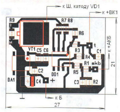
The controller circuit is shown in fig. 1. Its "heart" is the DD1 PIC12F675-I/SN microcontroller, clocked by an internal 4 MHz oscillator. The voltage is supplied to the microcontroller through a divider on resistors R1 and R2 directly from the positive terminal of the battery (+ battery). The temperature sensor VK1 (LM135Z) is also fixed on it. This is an analog sensor with linear voltage versus temperature (TKN = +10 mV/K). Capacitors C1 and C3 - noise suppression. The microcontroller, using the built-in ADC, converts the analog signal of the sensor into a digital code. The temperature measurement step in the program is 2 °C. Based on the value obtained, the program calculates the desired voltage.
The calculation is based on the loaded table built according to the graph shown in fig. 2. The calculated voltage is compared with the real one on the battery, and if it is less than necessary, then the microcontroller turns on the excitation winding (OB) of the car generator. To exclude multiple switching at threshold voltages, a hysteresis of about 0,2 V is provided between turning on and off the OF. The winding is controlled by a key on a field-effect transistor VT1 IRLR2705. To improve the reliability of the device and accelerate the switching of the transistor VT1, the gate of the latter is connected immediately to two outputs GP4 and GP5 of the microcontroller DD1. The microcontroller is powered by +5 V from the integral stabilizer DA1 L78L05CD. The same voltage is also used as a reference voltage for the internal ADC of the microcontroller. The drain of the transistor VT1 is connected to the wire going to the terminal Ш, and through the diode VD1 - to the wire going to the terminal B of the standard relay-regulator (see the wiring diagram of the VAZ-2109 car). The current consumption of the device is about 4 mA.
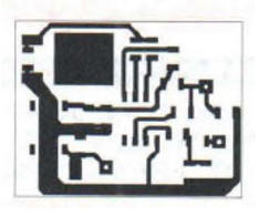
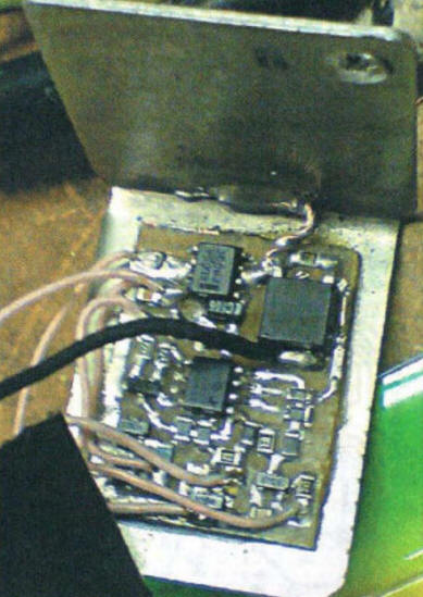
The printed circuit board is made of one-sided foil fiberglass with dimensions of 27x21 mm. The board drawing is shown in fig. 3, and in fig. 4 - arrangement of elements on a scale of 2:1. All resistors and non-polar capacitors are for surface mounting, size 0805, C4 - tantalum oxide, size A or B. Wires with a standard four-pin block at the end are soldered to the contact pads on the board. The assembled regulator is placed in the body of the standard relay-regulator of the VAZ-2109 car of the old model. The case was carefully opened, and a new one was glued in place of the old board. The LM135Z temperature sensor is glued to a thick brass washer with thermally conductive adhesive. This washer is then fixed with a bolt securing the positive wire to the battery terminal. The power wire of the device, coming from clamp B, is also soldered to it. There is no ICSP connector for programming, so the microcontroller must be programmed in advance or the programmer connector must be connected to the corresponding printed pads on the board with thin wires.
The appearance of the assembled regulator is shown in fig. 5. It must be adjusted at a temperature of +20 ° C before installation in the housing. The temperature sensor VK1 and the resistor R1 are turned off, a voltmeter (preferably digital) is connected to the gate of the transistor VT1. Next from regulated power supply supply a voltage of +13,8 V to the input of the stabilizer DA1 and check the presence of a voltage of +5 ± 0,1 V at its output. The gate VT1 must be a high logic level. Connect the output of the resistor R1. At this point, the high logic level at the gate of VT1 should change to low. A selection of resistor R2 achieves a clear appearance of a high level at a voltage of 13,6 V and a low level at 13,8 V. Then the output of the temperature sensor VK1 is connected. At +20 °С, the switching threshold should be 14 ... 14,2 V. By connecting a low-power 12 V lamp between the drain of the VT1 transistor and the plus of the power source, make sure that the transistor switches correctly when the supply voltage changes. On this, the adjustment can be considered complete. When installing on a car, it is necessary to ensure that the wires from the regulator are not near high-voltage ones, and also protect the terminal block from water and dirt. It is advisable to use shielded wires for the power circuits and the temperature sensor. This voltage regulator has been in operation on the car for two years now, and no failures have been noticed. During severe Siberian frosts, the battery gave noticeably more current to the starter, and on hot days it did not recharge. The microcontroller program and PCB drawing in Lay format can be downloaded from ftp://ftp.radio.ru/pub/2013/04/termoreg.zip. Author: N. Ovchinnikov
Artificial leather for touch emulation
15.04.2024 Petgugu Global cat litter
15.04.2024 The attractiveness of caring men
14.04.2024
▪ Budget 8" tablet Archos 80 Xenon on Android 4.1 ▪ Compact amateur 4K camcorder Sony Handycam FDR-AX100E ▪ Plant stress measuring device
▪ section of the site Audio and video surveillance. Selection of articles ▪ article by Leszek Kumor. Famous aphorisms ▪ article What are Sprains, Tendon Sprains and Bruises? Detailed answer ▪ article Irga round-leaved. Legends, cultivation, methods of application ▪ article Halogen bulbs last longer. Encyclopedia of radio electronics and electrical engineering ▪ article Fingerprints - how to make them visible. Chemical experience
Home page | Library | Articles | Website map | Site Reviews
www.diagram.com.ua |


 Leave your comment on this article: