|
|


 Arabic
 Bengali
 Chinese
 English
 French
 German
 Hebrew
 Hindi
Hindi Italian
 Japanese
 Korean
 Malay
Malay Polish
 Portuguese
 Spanish
 Turkish
 Ukrainian
 Vietnamese
|
ENCYCLOPEDIA OF RADIO ELECTRONICS AND ELECTRICAL ENGINEERING One antenna is not enough ... Encyclopedia of radio electronics and electrical engineering
Encyclopedia of radio electronics and electrical engineering / Antennas. Measurements, adjustment, coordination I gradually came to this conclusion. And here's the thing. To watch TV programs, active combined M V / DM V antennas (AKA) with reduced dimensions are most often used. A lot of AKA designs can be divided into two groups: for external installation (external) and internal (indoor). The AKA installed outside my window at the level of the 4th floor of a brick building ensured satisfactory reception of all programs in UHF channels and on MB channel 11 (12 out of 15 programs broadcast in Tyumen), which cannot be said about the 3 remaining programs on MB ( 1, 3 and 9 channels). Channel 3 especially "suffered": the multi-contour image due to numerous signal reflections sometimes led to complete incomprehensibility of the picture on the screen. The same "illness", but only to a lesser extent, was also observed on channel 1. And the signal on channel 9 came at an insufficient level, and the TV collected various kinds of local interference because of this. How to deal with this? Having some experience with phased circuits and having worked through the material on interference noise suppression [1, 2], I decided to experiment. To begin with, I purchased a TV signal adder (Splitter) "BLACKMOR C3" in a radio goods store, which has two MB inputs and one UHF. and the second AKA (MV / UHF) in the room version, which is a combination of a log-periodic 6-element UHF antenna and a dipole MB. Turning on both antennas simultaneously through the adder, I found out that the "combination" works most efficiently on all channels when the external AKA is connected to the adder socket "DMV". and room - in one of the sockets "MB". Power was supplied to both antennas. During the experiments, the outdoor antenna remained in a fixed position, directed at the TV center, located at a distance of 10...12 km. The indoor antenna moved: its orientation in azimuth, elevation and polarization changed. These manipulations made it possible to obtain a very high quality image without multicontours and interference in all 15 programs, but, unfortunately, in different positions of the room ACA. The conditions for low-frequency channels (the same 1 and 2 MB) turned out to be especially critical. But a compromise location for installing AKA (with some deterioration in image quality on individual channels) can still be found. It has been said that a system of two AKA can suppress local interference to some extent. if we operate with an additional signal (due to the action of the AGC of the TV) and the phase noise compensation method described in [9]. The difference in the frequency response of the adder over the inputs should not be discounted. If you want to receive TV signals from different directions, then you need to rotate the outdoor antenna. There are several ways to rotate the antenna:
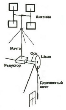
I want to note one important feature: the AKA system as a phase-compensating (common-mode) system will only work at a small distance of the AKA from each other (the higher the frequency, the shorter this distance should be) in order to fulfill the conditions for phase summing the signal from both antennas. At a large distance AKA on the TV screen, an irreparable repetition of the image and, under certain conditions, even a breakdown in synchronization can occur. In this case, it is better to turn on two indoor antennas through the adder (if the signal level of the television center at the reception point allows). By spreading them in space and mutually orienting, you can compensate for local interference, increase the signal and improve the reception quality of the desired program. For long-range reception of TV signals, something similar to a phased antenna array (PAR) can be assembled from AKA, i.e. arrange the antennas as in-phase elements in the same plane and at a certain distance from each other, depending on the frequency. The signals from each ASC are reduced to a common reduction cable through an adder, the ASC amplifiers are powered through a reduction cable or by separate wires. To suppress local interference, one of the ASC (auxiliary) is sent to its source. The position of this ASC is selected according to the maximum suppression of interference, the signal of which is in antiphase with the signals from the main ASC. To be completely accurate, then for the complete destruction of interference, amplitude balancing of the signals will also be required. I do not think that this will become an insurmountable obstacle for someone who decides to "finish off" once and for all the annoying hindrance. When experimenting with antennas, you will most likely have to rotate the external antenna as well. If it is located near the window, I can recommend a simple turning mechanism, which I “peeped” from a familiar radio amateur back in my youth. Figure 1 schematically shows a manually operated rotary assembly. It consists of a mast on which the antenna is mounted, a gearbox with a rotation angle of 90 °, an elongated axle, a pulley and a wooden pole hinged to it.
To turn the antenna, it is enough to put your hand in the Fold in front of which the end of the pole hangs, take the pole with your hand and, slightly tilting, reciprocate (up and down). A kind of crank mechanism (like the wheels of a steam locomotive) obtained from a pole and a pulley converts the shocks of the pole into a rotational movement of the shaft, which is transmitted to the antenna mast through a gearbox with deceleration. After half a century, it is difficult to judge some of the design details, but the main thing here is the idea! Antenna position indication can be done (along with other methods) with a simple mechanical rev counter. Author: V.Besedin, Tyumen
Artificial leather for touch emulation
15.04.2024 Petgugu Global cat litter
15.04.2024 The attractiveness of caring men
14.04.2024
▪ Microsoft Surface Duo 2 foldable smartphone ▪ Extreme Smartphone Ulefone Armor 12 5G
▪ section of the site Wonders of nature. Article selection ▪ article by Oswald Spengler. Famous aphorisms ▪ article How long did the longest war in European history last? Detailed answer ▪ article Chips for radio modems. Encyclopedia of radio electronics and electrical engineering
Home page | Library | Articles | Website map | Site Reviews
www.diagram.com.ua |

 Leave your comment on this article: