Simple and compact vertical antenna for CB band. Encyclopedia of radio electronics and electrical engineering

Encyclopedia of radio electronics and electrical engineering / Antennas. Measurements, adjustment, coordination
 Comments on the article
Having worked for more than 30 years as a foreman of a radio workshop engaged in the repair of communication radio equipment with a traveling nature of work, I have repeatedly come across a situation where a compact antenna was required that can be easily transported and installed, for example, on a balcony, loggia, in a window opening or on the luggage superstructure of a car . In particular, such an antenna was needed for on-air testing of civil CBS radio stations in the 27 MHz band.
From a constructive point of view, the most optimal option for such an antenna seemed to me to be a shortened vertical radiator with an extension coil.
The vibrator of my antenna (Fig. 1), or rather, its element "a", is made of a telescopic tube from an old indoor television antenna "KTTA" (the so-called "whiskers"). This makes it possible, by changing the length of the vibrator, to quickly rebuild the antenna over the range, which is essential because of its narrow bandwidth.
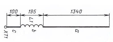
Fig. 1
The extension coil L1 (element "0") is wound with a copper wire with a diameter of 1,2 mm in PVC insulation (outer diameter over the insulation - 4 mm) on a frame made of a plastic pipe with a diameter of 25 mm (photo in Fig. 2).

Fig. 2
Winding - turn to turn, for a length of 195 mm. Element "c" of the antenna is formed by the lower output of the coil.
Matching the high impedance of the antenna with the low wave impedance of the feeder (and all modern industrial communication equipment is designed to operate on a load with a wave impedance of 50 ohms) is performed by the P-loop (Fig. 3).
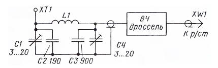
Fig. 3
It is mounted in a metal case from the antenna filter of the VHF radio station "Granit" (Fig. 4).

Fig. 4
Trimmer capacitors C1 and C4 with an air dielectric are also from this radio station. Capacitor C2 is made up of three capacitors KT-2 with a capacity of 30 pF + 82 pF + 82 pF, connected in parallel. Capacitor C3 is made up of three KT-2 capacitors with a capacity of 300 pF, also connected in parallel. When choosing capacitors, one should take into account the maximum power of the equipment with which to work. With a power of 50 W, their operating voltage must be at least 500 V.
Coil And matching device contains 8 turns of silver-plated wire with a diameter of 1,5 mm, wound turn to turn on a mandrel with a diameter of 9 mm and then stretched to a length of 20 mm.
To prevent the antenna effect of the feeder between the radio station and the matching device, a blocking choke is included. It consists of several turns of the same cable, wound on a ferrite annular magnetic circuit of suitable sizes with an initial magnetic permeability of 400 or more. The number of turns should be determined experimentally from changes in SWR, caused, for example, by moving the feeder, touching it with your hand or the body of the SWR meter. With good agreement and optimally selected number of turns, these changes are insignificant.
This operation should be carried out after preliminary tuning of the elements of the P-loop for a minimum SWR, for example, using an antenna analyzer MFJ-259. In this case, the section of the CB range should be selected, where at this moment the least pickups on the analyzer are noted.
The test results showed that the antenna bandwidth at SWR not more than two is approximately equal to 120 kHz. Narrow bandwidth is often considered a disadvantage of an antenna. But in this case, due to the fact that the antenna can be tuned in range, the narrow band is rather its advantage, as it reduces out-of-band interference from closely operating radio stations during reception and reduces spurious emissions during transmission.
Capacitor C1 can change the resonant frequency of the entire system within small limits without changing the geometric dimensions of the vibrator. A similar antenna can be designed for the HF band of 10 meters
Author: V. Efremov (UA6HGW), Essentuki, Stavropol Territory
 See other articles Section Antennas. Measurements, adjustment, coordination.
Read and write useful comments on this article.
<< Back
 Latest news of science and technology, new electronics:
A New Way to Control and Manipulate Optical Signals
05.05.2024
The modern world of science and technology is developing rapidly, and every day new methods and technologies appear that open up new prospects for us in various fields. One such innovation is the development by German scientists of a new way to control optical signals, which could lead to significant progress in the field of photonics. Recent research has allowed German scientists to create a tunable waveplate inside a fused silica waveguide. This method, based on the use of a liquid crystal layer, allows one to effectively change the polarization of light passing through a waveguide. This technological breakthrough opens up new prospects for the development of compact and efficient photonic devices capable of processing large volumes of data. The electro-optical control of polarization provided by the new method could provide the basis for a new class of integrated photonic devices. This opens up great opportunities for ... >>
Primium Seneca keyboard
05.05.2024
Keyboards are an integral part of our daily computer work. However, one of the main problems that users face is noise, especially in the case of premium models. But with the new Seneca keyboard from Norbauer & Co, that may change. Seneca is not just a keyboard, it is the result of five years of development work to create the ideal device. Every aspect of this keyboard, from acoustic properties to mechanical characteristics, has been carefully considered and balanced. One of the key features of Seneca is its silent stabilizers, which solve the noise problem common to many keyboards. In addition, the keyboard supports various key widths, making it convenient for any user. Although Seneca is not yet available for purchase, it is scheduled for release in late summer. Norbauer & Co's Seneca represents new standards in keyboard design. Her ... >>
The world's tallest astronomical observatory opened
04.05.2024
Exploring space and its mysteries is a task that attracts the attention of astronomers from all over the world. In the fresh air of the high mountains, far from city light pollution, the stars and planets reveal their secrets with greater clarity. A new page is opening in the history of astronomy with the opening of the world's highest astronomical observatory - the Atacama Observatory of the University of Tokyo. The Atacama Observatory, located at an altitude of 5640 meters above sea level, opens up new opportunities for astronomers in the study of space. This site has become the highest location for a ground-based telescope, providing researchers with a unique tool for studying infrared waves in the Universe. Although the high altitude location provides clearer skies and less interference from the atmosphere, building an observatory on a high mountain poses enormous difficulties and challenges. However, despite the difficulties, the new observatory opens up broad research prospects for astronomers. ... >>
| Random news from the Archive Electronic wine taster
26.12.2023
Daegu Gyeongbuk Institute of Science and Technology (DGIST), led by Professor Kyun-In Jang from the Republic of Korea, presents an innovative electronic wine taster. This remarkable instrument, developed by the research team, is capable of accurately simulating taste sensations and analyzing saltiness, acidity, bitterness and sweetness in real time.
New technology promises to improve not only the wine tasting process, but also enrich the consumer experience in various areas.
The device is based on 4 sensors, each of which specializes in a specific taste. Just a few millimeters in size, these sensors function as taste buds, capable of detecting and analyzing various chemicals, converting them into electrical signals. The authors note that similar systems have been created previously, but they lacked the “brain” to process combinations of flavors in real dishes and drinks.
To cope with these challenges, scientists have developed integrated e-tongue systems that combine sensors and deep learning technologies. Experiments carried out on 6 different types of wine confirmed the high efficiency of the device, which was able to classify wines with an accuracy of more than 95%. Thanks to deep learning, the device also offered recommendations for selecting similar types of wine, ideal for a variety of dishes.
The researchers are convinced that the electronic taster could find application in various industries, including food, liquor, cosmetics and pharmaceuticals. The introduction of this technology promises a revolution in determining taste characteristics and creating ideal combinations in various products.
|
Other interesting news:
▪ MAX14851 - universal 6-channel 600V digital isolator
▪ Nvidia AI systems for construction sites
▪ DEll Wasabi PZ310 Mobile Printer
▪ Atomic clocks will become even more accurate
▪ Western Digital's HDD capacity doubles
News feed of science and technology, new electronics
 Interesting materials of the Free Technical Library:
▪ section of the site Interesting facts. Selection of articles
▪ where Ek threw the article! Popular expression
▪ article Why does coffee taste different? Detailed answer
▪ video engineer article. Job description
▪ article Siren 110 dB on a 74C14 chip. Encyclopedia of radio electronics and electrical engineering
▪ article Standards for testing electrical equipment and devices for electrical installations of consumers. Complete switchgears for indoor and outdoor installation. Encyclopedia of radio electronics and electrical engineering
Leave your comment on this article:
 All languages of this page
Home page | Library | Articles | Website map | Site Reviews

www.diagram.com.ua
2000-2024


 Arabic
 Bengali
 Chinese
 English
 French
 German
 Hebrew
 Hindi
Hindi Italian
 Japanese
 Korean
 Malay
Malay Polish
 Portuguese
 Spanish
 Turkish
 Ukrainian
 Vietnamese