|
|


 Arabic
 Bengali
 Chinese
 English
 French
 German
 Hebrew
 Hindi
Hindi Italian
 Japanese
 Korean
 Malay
Malay Polish
 Portuguese
 Spanish
 Turkish
 Ukrainian
 Vietnamese
|
ENCYCLOPEDIA OF RADIO ELECTRONICS AND ELECTRICAL ENGINEERING Three-band directional antenna Spider. Encyclopedia of radio electronics and electrical engineering
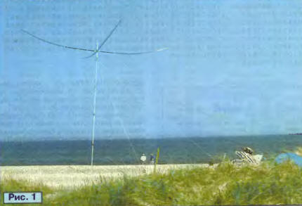
Encyclopedia of radio electronics and electrical engineering / HF antennas The idea of creating a very light and portable directional KB antenna, made of wire and stretched between telescopic glass-plastic rods, although not new, is increasingly attracting the attention of radio amateurs. The German shortwaver Cornelius Pohl (DF4SA) proposed a design variant in which three "wave channel" wire antennas are placed on one frame of four rods - two three-element for 20 and 15 meters and one four-element for a range of 10 meters. The antenna, despite its portability and low weight, has very good characteristics in terms of directivity factor and radiation pattern. Interest in the DF4SA antenna is great, therefore, with the permission of its creator, we provide a description of the "Spider". Introduction. "Spider" ("Spider") is a full-size tri-band, very lightweight antenna, built from glass-plastic rods and wire. The total antenna weight of approximately 5,5 kg makes it ideal for use in the field. A photograph of the antenna raised on a ten-meter aluminum mast is shown in fig. 1.
Any light telescopic masts and rotary devices from television antennas are suitable for the antenna. Wind loads on the antenna are small. It is easy to assemble and install by one person. The size of the folded and packed antenna does not exceed 1,2 m. A simplified (directors and reflectors in the same plane) sketch of its design is shown in fig. 2.
In terms of gain (gain) G and forward/backward radiation ratio (F/B), the "Spider" is not inferior to other full-sized antennas, including stationary ones. The permissible radiation power in continuous mode is 2 kW. The main data of the antenna are shown in Table 1.
The main task when installing the antenna is to raise it to the highest possible height. Antennas with even a small gain, raised to a high height, give a better signal than antennas with a large gain, but installed at a low height. The small weight of the "Spider" makes it easier to lift it to a great height. It also simplifies the selection of the optimal installation location. It is convenient to use the antenna when traveling, to install it on the tops of the surrounding mountains, on islands, towers of castles and lighthouses, and even on any roof. This antenna compares favorably with conventional heavy tri-band "beams". The assembly of the antenna is simple; no special complex elements are used in the design. The lack of a tuning procedure makes the antenna accessible to beginners. The cost of materials for the manufacture of the antenna is low, and you can still save on the mast and rotary device. The development of the antenna was facilitated by familiarity with the original and elegant solution of Dick Bird (G4ZU), who proposed his "Bird Yagi" - a three-element "wave channel" antenna with a V-shaped wire director and a reflector. It is also called "Bow and Arrow". However, there were no descriptions of multi-range designs in the literature, so the DF4SA had to take on independent development. After countless attempts at computer simulation, finally, it was possible to obtain a virtual antenna that satisfies the requirements. Structural, mechanical problems remained: the antenna had to be light but rigid, provide moisture protection, have repeatable electrical characteristics no matter how many times it was assembled and disassembled. The assembly should not have been difficult and did not require any special tools. All these requirements were met and the author enjoyed watching how the antenna easily weathered a fierce storm while operating from STZEE during the 2002 CQ WW CW CONTEST. Basic principles of building an antenna. "Spider" is a wave channel for 10, 15 and 20 meters. It is formed by three wire antennas nested one inside the other, stretched on a common fiberglass cross ("spider"). These antennas, in turn, contain three elements for the 20 meter range, three elements for the 15 meter range, and four elements for the 10 meter range. The active element of the antenna consists of three individual dipoles for the 20, 15 and 10 meters bands, interconnected only at the feed point. As a result, no coils or circuits ("ladders") are used in the design of the antenna. For the transition from an unbalanced coaxial cable to a balanced dipole, a simple and wide-band choke device proposed by W2DU was used. This makes the power system very simple and reliable. No phasing lines or other matching devices are required. The general sketch of the antenna (top view) and the installation dimensions of the elements (in centimeters) are shown in fig. 3.
The lengths of the wires (in centimeters) of the passive elements of the antenna are given in Table 2.
It should be noted that these data are valid only when the antenna is made of copper or copper-plated wire with a diameter of 1 mm without insulation. Other types of wires, especially insulated wires, will require some correction in the dimensions of the elements, which is associated with a change in the velocity factor, which, in turn, depends on the speed of wave propagation along the wire. Correction may also be necessary when using insulators at the ends of the antenna wires. Maintaining the exact dimensions of the antenna during its manufacture is very important. An error of even one centimeter (!) Will lead to a change in the parameters. It follows from the above that the antenna wires should not be pulled out under load. It is best to use copper-plated steel wire, data on which can be found in [1]. When the first copy of the antenna was made of ordinary soft copper wire with enamel insulation, some elements during assembly and disassembly of the antenna were stretched even by 10 cm, which caused the resonant frequencies to "leave" and the radiation pattern deteriorated. The ratio of radiations forward/backward suffered especially. The design of the active element is shown in fig. 4. It consists of three dipoles, which must be located in a vertical plane, strictly one above the other. As with other multi-range dipoles, the farther they are from each other, the less their interaction.
The distance between the upper 20m dipole and the lower 10m dipole should be about 50cm. It is also important that the 10m dipole is extended at least a few centimeters from the fiberglass carrier pipe. Otherwise, the SWR may fluctuate somewhat when the fiberglass rod gets wet from the rain. Dipole lengths (in centimeters) are given in Table 3.
The balancing device ("balun") can be very simple, since the input impedance of the antenna at the feed points is already close to 50 ohms. Therefore, no resistance matching is required. All that is needed is to switch from an unbalanced coaxial power cable to a balanced antenna. Therefore, instead of the toroidal transformer, it was possible to use a simple coaxial cable choke in this antenna. The simplest version of a coaxial cable choke is a coil of a few turns (5...10) directly near the feed point. However, the operation of such a choke is highly dependent on the frequency, the type of cable itself, the diameter and length of the coil. Another problem arises if the winding diameter is less than allowed for a given type of cable - over time, the cable parameters deteriorate. A much better solution is to use a coaxial choke as described by W2DU [2]. It is necessary to take a piece of thin coaxial cable and put on its outer insulation several (from 16 to 50, depending on the type) ferrite rings, which effectively increase the impedance for currents flowing along the outer surface of the braid. As a result, these currents are significantly reduced. If you use a piece of cable with fluoroplastic (Teflon) insulation, then the allowable power supplied to the antenna can reach two kilowatts. A piece of cable with ferrite rings put on it is placed in a waterproof box made of a box-shaped plastic profile with a lid. A standard S0239 type cable connector is mounted on one end of the box, and two bolts for connecting the halves of the active element are mounted on the other end. The design of the balancing device with the cover removed is shown in Fig. 5.
The device also performs another function: attached to the mast, it raises the feed point of the active element above the central connection of the load-bearing fiberglass elements. Antenna design. Its basis is the central connection shown in Fig. 6.
It is made of two square plates of sheet duralumin and four pieces of pipes (Fig. 7), into which load-bearing fiberglass elements are inserted.
Pipes are clamped between the plates with eight screws, oblong holes in the plates allow you to adjust the connection to a specific mast diameter, which can be from 30 to 60 mm. The connection is additionally rigidly attached to the mast with a piece of U-shaped duralumin profile (it is attached with two bolts to the top plate) and a U-shaped clamp with nuts. The design of the central node ensures the location of the center of gravity of the antenna exactly along the axis of the mast, which reduces the load on the mast and the rotator. Bearing fiberglass elements 5 m long are the lower sections of nine-meter fiberglass rods. To stiffen the entire supporting structure, a series of guy wires made of 1,5 mm diameter Kevlar string was used - a method well known since the days of the sailing fleet. The string withstands breaking up to 150 kg. Kevlar is good in that it practically does not stretch, and the antenna retains its shape during rotation and with significant wind loads. The bracing configuration is shown in fig. 8. For their fastening, it is recommended to use sail knots that hold the load well and are easily untied when dismantling the antenna.
After assembling the supporting structure, wire elements are easily and quickly attached to it. In places where they are bent, as well as at the ends, short pieces of plastic insulating tubes are put on the elements. Results and technical data. The antenna was raised on a ten-meter mast in an open area, and its parameters were carefully measured. It turned out that the used copper-plated steel wires with a diameter of 1 mm do not require the introduction of a velocity factor, and the data obtained from computer simulation can be used directly in the manufacture of the antenna. It also turned out that the insulators at the ends of the wires (polyamide tubes 4 cm long, filled with epoxy resin) noticeably affect the resonant frequency of the elements, lowering it by about 100...200 kHz. This effect must be taken into account by shortening the wires accordingly. The results of measurements of the gain and the ratio of radiation forward/backward and forward/sideways are shown in Table 4. The gain values are given relative to an isotropic radiator, and in parentheses - relative to a dipole. Approximately the same values were obtained as for a typical modern three-band antenna with a carrier traverse (boom) length of 6 ... 7 m.
The values of the radiation ratio forward/sideways are somewhat smaller, due to the fact that the active elements do not lie in the same horizontal plane as the passive ones. However, this has some merit: when searching in a range, the operator, although weakly, hears signals coming from other directions. As an example, in fig. Figure 9a shows the antenna patterns at 14,12 MHz in the azimuth and vertical planes, calculated using the NEC antenna simulation program. The calculation was made for an antenna installation height of 10m above the Earth's surface. On fig. Figure 9b shows similar radiation patterns when the antenna is installed at a height of 20 m. Graphs of fig. 9c show the gain and forward/backward radiation ratio as a function of frequency.
During field work in various expeditions, the "Spider" fully justified the hopes placed on it. Further information about the antenna and a detailed description of its manufacturing technology can be found on the DF4SA website [3]. Some useful discussions of the construction, as well as translations of the description into other languages, are available at [4]. The antenna was also modeled using the MMANA antenna simulation program. The results obtained differ little from those given above. Literature
Machine for thinning flowers in gardens
02.05.2024 Advanced Infrared Microscope
02.05.2024 Air trap for insects
01.05.2024
▪ Inexpensive protection of automotive electronics from cyber attacks ▪ Coca-Cola, Apple and IBM are the world's best brands ▪ The dangers of 5G communications for the health of bees ▪ Earth's lakes are evaporating faster than thought
▪ site section Electric motors. Article selection ▪ article Malevich Kazimir Severinovich. Famous aphorisms ▪ article How do parrots speak? Detailed answer ▪ article Content manager (website editor). Job description ▪ article Automated energy saving. Encyclopedia of radio electronics and electrical engineering
Comments on the article: Vladimir Great! Thanks for the info!
Home page | Library | Articles | Website map | Site Reviews
www.diagram.com.ua |


 Leave your comment on this article: