|
|
ENCYCLOPEDIA OF RADIO ELECTRONICS AND ELECTRICAL ENGINEERING Radio beacon of 1300 and 2400 MHz bands. Encyclopedia of radio electronics and electrical engineering
Encyclopedia of radio electronics and electrical engineering / VHF antennas Currently, radio amateurs are increasingly mastering the VHF bands of 1296 and 2400 MHz. The latter, for example, is used to receive signals from the repeater of the AO-40 amateur radio satellite. Setting up the equipment and antennas of the high-frequency VHF bands is greatly facilitated by low-power transmitters - radio beacons. The scheme of the radio beacon is shown in fig. 1. It consists of a master oscillator with quartz frequency stabilization, assembled on a transistor VT1, a buffer amplifier on a transistor VT2 and two varactor frequency multipliers using the capacitances of the collector junctions of transistors VT3 and VT4. The required harmonics are extracted by the L3C12 (2400 MHz) and L4C13 (1300 MHz) resonant circuits. Antennas are connected to coaxial female connectors XS1, XS2. The generator and amplifier are powered by a GB1 battery through an integrated voltage regulator assembled on a DA1 chip.
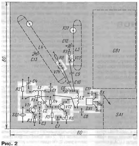
The device works like this. The master oscillator is excited at the frequency of the quartz resonator, in this case 100 MHz, included in the base circuit of the transistor VT1. An L1C4 circuit is installed in the collector circuit of the transistor, and a positive feedback signal is fed to the emitter circuit through a capacitive divider C2C3. The signal from part of the turns of the coil L1 is fed to a resonant amplifier made on the transistor VT2. Its gain can be smoothly changed by resistor R6. The amplified signal from the L2C6 circuit is fed to the varactor frequency multipliers. The 24th harmonic of the signal (2400 MHz) is generated on the nonlinear capacitance of the collector junction of the transistor VT3, is allocated by the L3C12 circuit and fed to the output connector XS1. Quite similarly, the 13th harmonic (1300 MHz) arises in the circuit of the nonlinear capacitance of the collector junction of the transistor VT4 and is highlighted by the L4C13 circuit. Half-wave resonators are used in these resonant circuits. Most of the details of the beacon are placed on a printed circuit board made of double-sided foil fiberglass with a thickness of 1,5 ... 2 mm, a sketch of which is shown in fig. 2. A metal screen with a height of at least 20 mm is installed along the edge of the board, which is closed with a metal cover. The switch is installed on the screen, and the output connectors are directly on the board.
In the device, in addition to those indicated in the diagram, it is permissible to use the following parts: a power stabilizer chip - 78L05, transistors VT1 and VT2 - KT368B, VTZ and VT4 - KT3101A. Trimmer capacitors C4 and C6 are used of the type KT4 - 25, C12 and C13 - KT4 - 27 (without leads), constant capacitors - K10 - 17v (without leads) or K10 - 17a with leads of the minimum length. Trimmer resistor - type SPZ - 19, fixed resistors - MLT, P1 - 4, P1 - 12. Coils L1 and L2 are frameless, they are wound with wire PEV - 2 0,6 on a mandrel with a diameter of 5 mm and contain 6 turns with taps from 1 and 2,5 turns and 2,5 turns, respectively, counting from the output connected to the power wire. Half-wave resonators L3 and L4 are made of a strip of copper (preferably silver-plated) foil 0,5 mm thick and 6 mm wide in the shape of the letter "P". The top part has a length of 25 mm (L3) and 45 mm (L4), the side parts are 5 mm. Connectors are connected to the top at a distance of 3 mm from the sides, and transistors VT3 and VT4 - at a distance of 5 mm, as shown in fig. 2. Trimmer capacitors are soldered vertically in the middle of the top. The output connectors are of the SMA type or similar, necessarily high-frequency, coaxial. Switch SA1 can be any, small. The device is powered by a 9 V battery of the "Krona", "Korund", "Nika" type or similar, the current consumption is 10 ... 12 mA. As an antenna, you can use quarter-wave pieces of hard wire or half-wave vibrators, the design of which is shown in Fig. 3. They are made from pieces of cable PK50-2-22 or similar. Vibrator 1 is made from a length of 55 (2400 MHz) or 105 mm (1300 MHz). At the ends of the segments, the cable is stripped by 1,5 ... 2 mm, the braid and the central conductor are interconnected by soldering.
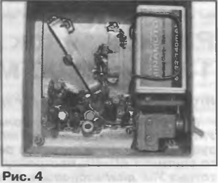
In the middle of the vibrator, at a length of 4...5 mm, the outer insulation is removed and the braid 2 is carefully cut so that a gap between its parts is about 2 mm. Then the braid in the place of the cut is tinned and the second feeder section of cable 3 with connector 4 at the end is soldered to it - the braid is to one side of the vibrator, and the central conductor is to the other. The recommended length (together with the connector) of the feeder sections is 90 (2400 MHz) and 165 mm (1300 MHz). A photograph of the mounted radio beacon (with the top cover removed) is shown in fig. 4.
Establishing a beacon begins with setting up a master oscillator and a buffer amplifier. The tuning resistor R6 is set to the middle position, the trimmer capacitor C4 achieves stable generation, and with the trimmer capacitor C6 - the maximum signal at the output of the amplifier. Then, with tuned capacitors C12 and C13, half-wave resonators are tuned to the corresponding frequencies according to the maximum output signal at the frequency of the desired harmonic. In conclusion, resistor R6 sets the maximum level of harmonics at the outputs, while additional tuning of the circuits is carried out using tuned capacitors C4 and C6. If the amplifier will work unstably, then between the collector of the transistor VT2 and the tap of the coil L2, you must install a resistor with a resistance of 50 ... 100 ohms. The level of the output signal of the tuned beacon at a load of 50 ohms was 50...70 mV (1300 MHz) and 5...10 mV (2400 MHz). In most cases, such a signal is quite sufficient, since due to the high frequency (and, consequently, the small wavelength), it does not make much sense to remove the beacon at a great distance from the tuned equipment. Author: I. Nechaev (UA3WIA), Kursk
A New Way to Control and Manipulate Optical Signals
05.05.2024 Primium Seneca keyboard
05.05.2024 The world's tallest astronomical observatory opened
04.05.2024
▪ The light went out - the air became cleaner ▪ The talking scanner will speak the text ▪ The LED display will warn the driver about the appearance of a pedestrian ▪ An electric current will help you remember
▪ site section Acoustic systems. Article selection ▪ article A word in simplicity will not be said, all with a grimace. Popular expression ▪ article What is surge flood? Detailed answer ▪ article Weigher. Standard instruction on labor protection ▪ article Waterproof varnish. Simple recipes and tips ▪ article Luxembourg proverbs and sayings. Large selection
Home page | Library | Articles | Website map | Site Reviews www.diagram.com.ua |


 Arabic
 Bengali
 Chinese
 English
 French
 German
 Hebrew
 Hindi
Hindi Italian
 Japanese
 Korean
 Malay
Malay Polish
 Portuguese
 Spanish
 Turkish
 Ukrainian
 Vietnamese


 Leave your comment on this article: