|
|


 Arabic
 Bengali
 Chinese
 English
 French
 German
 Hebrew
 Hindi
Hindi Italian
 Japanese
 Korean
 Malay
Malay Polish
 Portuguese
 Spanish
 Turkish
 Ukrainian
 Vietnamese
|
ENCYCLOPEDIA OF RADIO ELECTRONICS AND ELECTRICAL ENGINEERING Skeletal slot antenna: myths and reality. Encyclopedia of radio electronics and electrical engineering
Encyclopedia of radio electronics and electrical engineering / VHF antennas Judging by foreign amateur radio literature, the slot-skeletal antenna is popular at frequencies above 20 MHz. In the published article, an attempt was made to answer the question - to what extent its coefficient of directional action, stated in the literature, corresponds to reality. In books on VHF antennas, the so-called skeletal-slot antenna has been repeatedly described, and all publications without exception reported its very high parameters, large directivity factor (CND), wide frequency band and ease of tuning. The idea of an antenna was proposed by J. Ramsey back in 1949 [1], its design is shown in Fig. 1, borrowed from [2]. The active element of the antenna consists of three parallel half-wave dipoles located three floors above each other. To reduce the dimensions of the antenna, the ends of the upper and lower dipoles are bent at a right angle towards the middle dipole and connected to it. From him they are excited. The middle dipole is made split and connected to a matching quarter-wave two-wire line, which simultaneously serves to mount the reflector. The reflector is made as a wave channel in the form of a single vibrator, the electrical length of which is somewhat greater than half a wave. The dimensions of the antenna in wavelengths and the values of the coefficient of shortening k, depending on the diameter of the conductors (tubes) d, are shown in Fig. . 1. By moving the feed point XX along the two-wire line, you can change the input impedance of the antenna from zero (near the reflector) to about 400 ohms (at the YY point near the active element).
The current distribution in the active element is shown in fig. 2. It can be seen that the antinodes (maxima) of the current are located just in the middle of the horizontal parts of the element, forming a three-story in-phase system. In the vertical parts of the active element, the currents are small and directed towards each other. In addition, there are four current nodes, so there is no radiation from the vertical parts in the far zone. Recall that in the far zone, the antenna pattern is almost completely formed. The distance to the far zone is several wavelengths. It is the greater, the more directivity factor of the antenna.
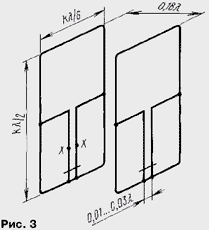
The active element of a skeleton-slot antenna can also be considered as two squares, combined by one side and feed points. However, compared to two full-size squares, the perimeter of the active element of the slot-skeletal antenna is somewhat smaller, probably due to the shortening effect of the capacitance between the vertical conductors of the element. A similar antenna was proposed by K. Kharchenko [3], but in it two squares are powered from the corners and combined by feed points. A simple skeleton-slot antenna has an insufficiently effective reflector. This drawback can be eliminated by making the reflector exactly the same as the active element (in the form of the same three-story vibrator design). Two-wire lines can no longer be placed between the elements, but no one bothers to draw them in the plane of each element to a point with zero potential in the middle of the lower horizontal vibrator. The result after this modification is shown in Fig. 3. The dimensions of the elements themselves remain the same, and the distance between the active element and the reflector is reduced to 0,18. This antenna has one more advantage. By moving the shorting jumpers along the two-wire lines, the elements manage to adjust it to the desired frequency, and by moving the reflector jumper, it is easy to tune the antenna to the maximum directivity factor or the front-to-back radiation ratio.
For such a two-element antenna, described in [2 and 4], an unusually high gain of 14...16 dB is reported! If the second of these books was not a serious publication, then you could still wave your hand and not take this figure seriously. But this book as a whole is very good and contains almost no errors. Its author, of course, could not test all the many constructions given in it. Therefore, if this is a mistake, then it appeared earlier, in some other editions, and it is now difficult to find the original source. It is quite clear that an in-phase system of vibrators should give a greater efficiency than a single vibrator, but the question is how much? Although in [2] on p. 100 and it is stated that the antenna "... is actually a six-element three-story in-phase", but the vibrators are quite close to each other, and also shortened. This will inevitably reduce efficiency. Thus, there were more questions than answers. In addition, radio amateurs familiar to the author were going to build just such an antenna for a range of 10 meters and were already ready to spend money on material, but now it is not cheap! In order to get a clear and precise answer to the question of SOI, an experiment was carried out in the 432 MHz band. The elements were bent in accordance with fig. 3 from pieces of enameled copper wire with a diameter of 1,5 mm, the connections are soldered, and the conductors of the lines at the installation sites of the closing jumpers and the cable connection are stripped of insulation. The whole structure was assembled on a wooden frame made of dry thin slats. The power cable ran from the power points along the conductor of the two-wire line to which the braid was connected, vertically down and connected directly to the output of the standard signal generator. A half-wave dipole with a detector and a microammeter served as the field indicator. It was located on a tripod at a distance of several meters from the antenna. The antenna was also fixed on a primitive swivel stand, which allowed its orientation to be changed. The antenna was tuned quite easily and quickly, just to the maximum radiation in the main direction. With the indicated dimensions at a frequency of 432 MHz, the distances of the closing jumpers from the base of the two-wire lines for the tuned antenna turned out to be as follows: for the reflector - 43 mm, for the active element - 28 mm. The distance to the connection point of the 50 ohm cable was 70 mm. When adjusted to maximum directivity, a small back lobe is detected. By adjusting the reflector, it can be suppressed almost completely. There was no radiation sideways, up and down. The directivity gain, more precisely, the gain of the antenna, equal to the product of directivity and efficiency, was determined as follows: the indicator marked the signal level generated by the antenna in the main direction, then instead of the antenna, a half-wave dipole located at the same point in space was connected to the power cable. The signal level from the generator increased enough to get the same readings on the indicator. The change in the signal level counted by the generator attenuator is numerically equal to the gain of the antenna relative to the half-wave dipole. For this antenna, it turned out to be 7 dBd. Relative to an isotropic (omnidirectional) emitter, it will be 2,15 dB more and will be about 9,2 dBi. Pay attention to the letters d and i in the designation of decibels - in the literature on antennas, it is customary to indicate in this way, relative to which radiator the directivity is measured. The width of the radiation pattern at half power was about 60° in the horizontal plane (in azimuth), and about 90° in the vertical plane (in elevation). With these data, the directivity factor can be calculated in another way: the solid angle into which the antenna radiates is equal to the product of the linear angles corresponding to the diagram width and expressed in radians. We get a value of about 1,5 steradians. At the same time, an isotropic antenna radiates into a solid angle of 4π, or 12,6 steradians. The gain, by definition, is the ratio of these solid angles and is 12,6/1,5 = 8,4 or 9,2 dBi. Having obtained such a good agreement between the directivity values determined by the two methods, the author decided that there was nothing more to measure and, with a slight disappointment, was once again convinced that miracles do not happen in antenna technology. Nevertheless, the antenna works very well and with small dimensions (330x120x120 mm in the 432 MHz band) provides a very decent gain. Literature
Author: Vladimir Polyakov (RA3AAE)
A New Way to Control and Manipulate Optical Signals
05.05.2024 Primium Seneca keyboard
05.05.2024 The world's tallest astronomical observatory opened
04.05.2024
▪ Internet speed doubled on the ISS
▪ site section Welding equipment. Article selection ▪ article Chizhik-pyzhik, where have you been? Popular expression ▪ article When does the famous Ring-a-ring o'roses date back? Detailed answer ▪ article Hill thyme. Legends, cultivation, methods of application ▪ article Multichannel amplifying device. Encyclopedia of radio electronics and electrical engineering
Home page | Library | Articles | Website map | Site Reviews
www.diagram.com.ua |


 Leave your comment on this article: