|
|


 Arabic
 Bengali
 Chinese
 English
 French
 German
 Hebrew
 Hindi
Hindi Italian
 Japanese
 Korean
 Malay
Malay Polish
 Portuguese
 Spanish
 Turkish
 Ukrainian
 Vietnamese
|
ENCYCLOPEDIA OF RADIO ELECTRONICS AND ELECTRICAL ENGINEERING Antenna UA6AGWv. 20-10 m. Encyclopedia of radio electronics and electrical engineering
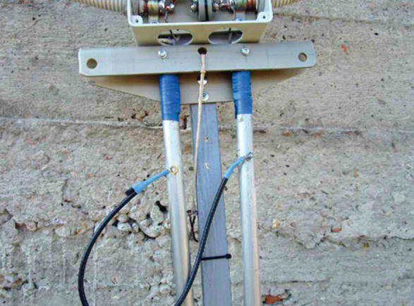
Encyclopedia of radio electronics and electrical engineering / VHF antennas This antenna (Fig. 1) operates in the frequency band from 14 to 29,5 MHz, which includes five amateur radio bands. The remote control system allows you to selectively adjust it to the desired range. The antenna is quite compact, and together with the mast it can be transported in the trunk or passenger compartment of a car. The length of any of its parts does not exceed two meters, and the diameter of the frame is less than one meter. The design of the antenna provides for its quick installation by one person in field conditions, for example, in a forest in a clearing, under trees, in a country house, on a rocky or sandy island, on board a small boat. Installation does not require braces, and yet the design easily withstands gusts of even storm winds.
The electrical circuit of the antenna practically does not differ from the previously published omnidirectional antennas of the UA6AGW design, for example [1]. The dimensions of this version of the antenna are shown in fig. 2. For operation in the frequency band 18 ... 29,5 MHz, the length of the beams is 1,6 m. To operate in the range 14 ... 18 MHz, the length of each beam should be increased to three meters, and an additional capacitor should be connected in parallel with capacitor C2 capacitance 25 pF. In the author's design, it is made of a piece of coaxial cable with a diameter of 8 mm with a wave impedance of 75 ohms. The use of an additional capacitor is due in this case to the insufficient maximum capacitance of the applied KPI. Given the availability of the antenna in field conditions, these operations are easy to perform.
The antenna frame is made of LCF12-50J S coaxial cable used in feeder lines at cellular stations. Its outer diameter is about 15 mm. The outer conductor ("braid") of the cable is made of a corrugated copper pipe with a diameter of 13,8 mm, the inner conductor is a copper pipe with a diameter of 4,8 mm. The space between them is filled with polyethylene foam. The black PVC jacket of the cable has been removed because the filler it contains creates significant losses at high frequency. The outer conductor ("braid") should be covered with several layers of protective varnish and put on top of it with a plastic corrugated electrical installation pipe. Each antenna beam is a telescopic structure consisting of two duralumin tubes with a diameter of 14 and 18 mm and a length of 1,55 m each. Grooves about 100 mm long and 1,5 ... 2 mm wide are sawn in the outer ends of pipes of a larger diameter, which contribute to reliable fixation of pipes of small diameter and ensure good electrical contact when deploying the beams to the working position for the 14 MHz band. Worm-drive clamps are also installed at the ends, with the help of which the inner pipes are clamped. Opposite ends of large pipes are fixed through movable hinges to a U-shaped plate bent from sheet vinyl plastic with a thickness of 3...4 mm (Fig. 3). The plate, antenna frame, communication loop and box with capacitors are fixed on a wooden beam with a section of 25x25 mm, which, in turn, is attached to the mast. Approximately at a distance of 100 mm from the inner ends, an M4 bolt with a nut is mounted in each pipe, which serve to connect an additional capacitor in the 14 MHz band. The mount of the beams allows you to turn them either in working or in the stowed position. When folded, the length of each beam is 1,6 m, when unfolded - about 3 m.
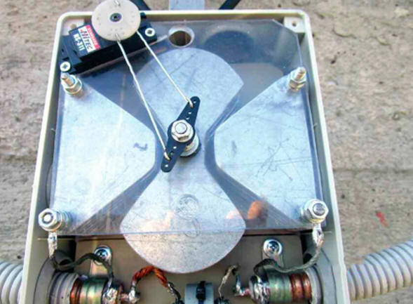
The beams are connected to the outer sheath cable of the frame with a bare stranded copper wire. Since soldering aluminum is a "troublesome" affair, four contact petals are riveted to the inner ends of large pipes to reduce the contact resistance with aluminum rivets. The wires connecting the rays to the frame are soldered to all four petals. The riveting and soldering points are protected from the weather by several layers of insulating tape. Capacitor C1 - K15U-1V 3,5 kV 4,7 pF 4 kvar. Capacitor C2 is a self-made butterfly type variable capacitance, consisting of six rotor and seven stator plates. Condenser dimensions - 115x130 mm. The plates are made of 0,5 mm thick galvanized steel sheet. The area of each stator plate is 24 cm2, the area of each rotor plate is twice as large. The condenser parts are assembled on M5 threaded studs, M5 nuts serve as spacers. The use of steel did not adversely affect the performance of the assembly. However, nothing prevents the use of other materials here. The author also tested a variant using the standard KPE-2, in which the rotor and stator plates were removed through one. Remote control of the variable capacitor C2 is carried out by the servo drive of the HiTec HS-311 steering machine, Standard size, used in car or aircraft models. For the mechanical connection of the servo drive and the capacitor, standard rocking chairs and wire rods were used (Fig. 4).
Capacitors C1, C2 and the servo drive mechanism are placed in a sealed plastic junction box with dimensions 140x200 mm for open wiring. To control the servo drive, a remote control panel (Fig. 5) is used, made on the basis of a servo tester with a digital indicator [2]. Commands to the servo drive are transmitted via UTP-4-C5e cable - twisted pair 4x2 for computer networks. Three pairs of wires are used (two wires connected in parallel).
The numbers on the indicator of the servo tester show the angle of rotation of the steering machine shaft. A table is fixed on the remote control case indicating which numerical value should be set on the indicator for antenna operation on a particular range and depending on the length of the beams (this table is compiled during the antenna tuning process). On the left side of the servo tester there is a "Select" button, when pressed, after setting the required value on the indicator, the steering servo shaft is rotated to the set angle. In the initial position, two of the three cable wires from the control panel to the steering machine are open. This is done in order to prevent spontaneous turning of the servo drive under the action of induced voltage. For the same purpose, a ferrite ring is put on the control cable at the point of its connection to the servo drive. When you press the "Select" button, the contacts are closed, and the servo shaft is set to the desired position. The time of rotation of the capacitor rotor from one extreme position to another is about a second, the positioning accuracy due to feedback is very high. To make it more convenient to control the servo tester, the standard angle adjustment knob has been replaced with a larger diameter knob. To power the servo tester, a stabilized DC voltage source from +4,8 to +6 V is required. With a supply voltage of +6 V, the control cable can be 50 meters or more long. The communication loop is made of a coaxial cable with a characteristic impedance of 50 ohms, which feeds the antenna. The main dimensions of the loop and the method of its manufacture are shown in fig. 6. At the end of the cable and in a place 400 mm away from it, the outer insulating PVC sheath was removed, and in the middle of this segment, both the sheath and the outer conductor - braid were removed for a length of 10 mm (Fig. 6). The inner conductor is soldered at the end of the cable to the braid. Then this end of the cable is applied to the second section with the outer insulation removed and soldered to it. The resulting loop is attached to the top of the antenna frame (see Fig. 3), which, in turn, is fixed to the rail with nylon cable ties. During installation, the top of the mast, the point of symmetry of the communication loop and the point of symmetry of the radiating frame must match. At the same distance to the left and right of the symmetry points (approximately 4...5 cm), the communication loop is attached to the radiating frame with cable ties. Symmetry in this place is important, it allows you to avoid the appearance of currents on the braid of the supply cable and work without "ground". The antenna is mounted on a mast about six meters high. It consists of three plastic pipes with a diameter of 42, 36 and 30 mm. The author used three sections of an eight-meter mast from the "Mast-8-2u" kit manufactured by R-QUAD. Initially, the antenna is assembled on the ground in a horizontal position, after which it is installed in a vertical position and fixed in the right direction with the help of props, which, in turn, are attached using metal stakes driven into the ground. These two-meter props are enough to securely fix the antenna.
At the stage of preliminary tuning of the antenna, it may be necessary to change the shape of the communication loop from round to elongated (oval), and vice versa, and to select the length of the beams. The criterion for optimal tuning should be considered the minimum value of the SWR (the author has no worse than 1,5) on the indicated ranges. The antenna is quite broadband, and when tuned to the middle of any amateur band, additional tuning, as a rule, is not required. SWR within the entire range should not exceed the value of 2, except, perhaps, only for the range of 10 meters. When working at its extreme frequencies, additional tuning may be required. The radiation pattern of the antenna in the horizontal plane has the form of an ellipse, elongated longitudinally to the rays, and does not have deep dips. The difference in the levels of the signal emitted in the direction of the beams and perpendicular to them is about 3 dB. The very first test of the antenna on a range of 10 meters made it possible to communicate with the island of Tasmania. Subsequently, many QSOs were made on different bands, and especially on 20 meters. In all cases, the antenna showed good performance. Literature
Author: Alexander Grachev (UA6AGW)
A New Way to Control and Manipulate Optical Signals
05.05.2024 Primium Seneca keyboard
05.05.2024 The world's tallest astronomical observatory opened
04.05.2024
▪ A concussion-surviving brain ages faster ▪ Static electricity amplifies sandstorms ▪ Ultra-cheap computer on a flash drive from Dell
▪ section of the site Factory technology at home. Article selection ▪ article Which of the creatures living on Earth is the oldest? Detailed answer ▪ article Psoralea drupes. Legends, cultivation, methods of application ▪ article Transceiver crystal filter. Encyclopedia of radio electronics and electrical engineering
Home page | Library | Articles | Website map | Site Reviews
www.diagram.com.ua |


 Leave your comment on this article: