
|
|
ENCYCLOPEDIA OF RADIO ELECTRONICS AND ELECTRICAL ENGINEERING Ultrashortwave antennas. Encyclopedia of radio electronics and electrical engineering
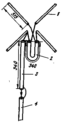
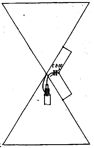
Encyclopedia of radio electronics and electrical engineering / VHF antennas Again and again, ultrashortwavers ask their senior colleagues: "Which antenna should I choose?" It is impossible to answer this question precisely, since it all depends on the purpose for which the antenna is being built. If connections are assumed in all directions, for example, within the city, then. very convenient antennas with a circular pattern, which often allow you to work at distances between stations equal to 50-100 km. Directional antennas are more suitable for long-distance communications. In "densely populated" areas with ultrashortwaves or in cases where there is interference from some directions, it is undoubtedly better to use highly directional antennas. These few examples are enough to understand that there is no antenna that is equally suitable for all cases. The radio amateur must himself choose an antenna that meets his basic requirements. Better yet, build two or three antennas and use them as needed. It is unreasonable for a novice ultrashortwave to choose as his first antenna some bulky and complex structure, in the process of building which, due to inexperience, he can make many mistakes. You should start with the construction of the simplest antennas and, as experience and knowledge grow, move on to more complex systems. When choosing the type of antenna, it is also necessary to take into account what basic materials are available to the designer. If it is not possible to purchase pipes or rods for antenna elements, then you can choose, for example, a "double square", which requires only wire, wooden slats and a small amount of insulating material to build. It is also essential how the supply line will be made - from a coaxial or ribbon cable, or simply in the form of a two-wire line. We must not lose sight of whether any measurements are needed when building an antenna. For a beginner, who also does not have measuring equipment, it is better to choose an antenna that will probably work well without tuning. Consider a number of types of antennas. Among them are simple designs that can be repeated by every beginner, and complex ones, including antenna systems, that may be of interest to more experienced DX hunters. Since most of our VHFs operate in the 144 MHz band, antenna dimensions are given for this band. The reader will note that no technical details of construction are given for any of the antennas. But this should not interfere with the construction, since the methods of work and many details are described in any ham radio handbook. CIRCULAR RADIATION ANTENNAS Cross dipole. The antenna consists of two half-wave vibrators 1 located at an angle of 90° to each other (Fig. 1). The radiation pattern of this antenna is far from being a perfect circle, but in practice it gives quite good circular radiation. Since the impedance of one dipole is approximately 70 ohms, when two dipoles are connected in parallel, the impedance is about 35 ohms. We do not have such a coaxial cable at our disposal, so it is best to feed the antenna through a quarter-wave transformer 3, made from a 50-ohm cable. A 75-ohm cable 4 runs from the transformer to the equipment. Balancing U-elbow 2 is made of the same cable.
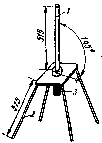
Vertical antenna (Ground Plane). Radiator 1 (Fig. 2) and radial conductors 2 provide a circular diagram in a horizontal plane. The angle between the radial conductors and the radiator determines the impedance of the antenna.
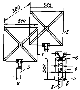
At an angle of 90 °, the wave impedance is approximately 30 ohms, at an angle of 180 ° - 70 ohms. Typically, an angle of 145° is chosen, which allows the antenna to be fed with a 50-ohm cable. The cable is connected to connector 3, mounted on a metal plate, to which radial conductors are electrically connected. The emitter, to which the central conductor of the cable is connected, is installed on insulator 4. DIRECTIONAL ANTENNAS "Double Square" This most popular directional KB antenna is also usable on VHF (Fig. 3, a). Its gain (compared to a half-wave vibrator) reaches 5,7 dB, the ratio of radiation forward / backward is 25 dB.
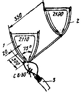
The distance between the active vibrator 1 and the reflector 2 is chosen to be 0,15 lambda, which makes it possible to feed the antenna with a 75-ohm coaxial cable 3. Experience has shown that the antenna fed in this way works quite satisfactorily. You can tune the antenna using a short-circuited loop included in the break of the reflector frame. To balance the antenna, you can use a quarter-wave glass (Fig. 3, b), connecting it to the ends of the active vibrator 1. The glass consists of a metal cylinder 4 with two covers - metal 5 and dielectric 6. Cable 3 passes inside the glass, the cable braid is connected to the cover 5. The diameter of the cup should be 3-4 times the diameter of the cable. For the manufacture of antenna elements, you can use a copper or aluminum tube, tape or wire of various diameters. "Double square" takes up very little space, structurally simple. This antenna has relatively good performance. Noteworthy is the possibility of placing antennas of different ranges on the same cross-shaped rails. Triangular Antenna (Delta Loop) belongs to the same family as "square", since the perimeter of the active vibrator is approximately equal to the wavelength. A feature of this antenna is that all elements of its design are metal. The author of the antenna advised to feed it with a 50-ohm coaxial cable, but a 75-ohm cable is also successfully used for this purpose. The simplest triangular antenna is shown in fig. 4. Active vibrator 1 is adjusted using a gamma matching device to which cable 3 is connected. Depending on the availability of measuring instruments, the adjustment is carried out according to the minimum SWR or the maximum signal strength. Reflector 2 can be made unregulated for simplicity.
UA1WW experimented a lot with a triangular antenna. He advises using 5- and 9-element options. The latter, due to the small horizontal angle of radiation, is particularly suitable for long-distance communications. A drawing of a 5-element antenna is shown in fig. 5. Here 1 is an active vibrator, 2 is a reflector, 3-5 are directors. Since this is a completely new antenna for our ultrashortwave antennas, here are some design data.
A 4-sided duralumin tube with a square side of 18-20 mm is most suitable for the bearing traverse; it is much more convenient to mount elements on it than on a round tube (see Fig. 6).
Antenna elements are made from a copper or aluminum tube or rod with a diameter of 6 mm, the horizontal side - from a wire with a diameter of 3 mm. The dimensions of the elements (in accordance with Fig. 6) are as follows:
triangular antenna - an object of interest for ultrashortwaves all over the world. Taking into account the positive experience with it, we can assume that it will soon become one of the most popular antennas. Therefore, we draw the attention of those wishing to experiment to one special type of it - a double triangular antenna (Fig. 7). The dimensions of the triangles of this antenna are slightly larger than those of a single one; the perimeter of the reflector is 2266, the active vibrator is 2116 and the director is 1993 mm. The distance between the reflector and the vibrator is 0,2 lambda, between the vibrator and the director is 0,15 lambda.
According to some data, the following gains of a double antenna were obtained (compared to a half-wave vibrator): one element (active vibrator) - 3-4 dB: two elements (vibrator and reflector) - 8-9 dB: three elements (reflector, vibrator in director), - 10-11 dB. It seems that this is a promising type of antenna and it is worth looking into. 10-element antenna (Yagi). Undoubtedly, this is the most popular VHF antenna (Fig. 8). It gives a gain of 13 dB. The author carried out with the help of such an antenna meteor communications with England and Belgium, many long-distance communications due to tropospheric passage and "Aurora".
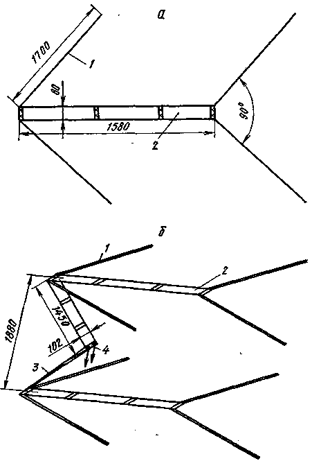
The passive elements of the antenna are made of a bimetallic wire with a diameter of 4 mm, and the active loop vibrator is made of a 15 mm copper tube and the same wire. The characteristic impedance at the feed point is 300 ohms, so the 75 ohm cable is connected through a U-bend, which is 68 cm long. The length of the bearing traverse is slightly more than 3,5 m, the diameter is 20 mm. The length of the reflector 7-1060, vibrator 2-990, directors 3-10 - respectively 933, 930, 927, 924, 921, 918, 915 and 912 mm. Antenna for multiple bands. There are circumstances when it is not possible to install more than one antenna. But in addition to an antenna, a radio station often needs a television one! Then the way out is a UKB antenna for several bands. One such antenna is shown in Fig. 9, a (top view) and 9, b (axonometric projection). It can be successfully used in the ranges from 50 to 220 MHz. The antenna gain at a frequency of 50 MHz is 7 dB, 144 MHz is 12 dB, and at 220 MHz it is even 13,5 dB. This antenna is double decker. At a frequency of 50 MHz, two corner vibrators 1 operate on each floor, located at a distance of lambda/4. At a frequency of 144 MHz, their length is approximately 3/4 lambda and therefore already a V-shaped antenna is obtained. At 220 MHz, the vibrators are 5/4 lambda long.
The vibrators are interconnected by two-wire lines 2, and both floors - by lines 3, the length of which, depending on the range, is from 1/4 to 5/4 lambda. The distance between the floors, if desired, can be changed within the limits allowed by the length of the lines 3. The input impedance of the antenna at the feed point 4 at frequencies of 50 and 144 MHz is about 300 ohms, at a frequency of 220 MHz it drops to about 200 ohms. Antenna elements can be made from a tube or rod: vibrators - 10 mm in diameter; lines 2 - with a diameter of 12 mm (10 mm is also possible, then the distance between the centers of the wires of the line should be chosen equal to 64 mm): lines 3 - with a diameter of 6 mm. Author: K. Kallemaa (UR2BU), Tartu; Publication: N. Bolshakov, rf.atnn.ru
The world's tallest astronomical observatory opened
04.05.2024 Controlling objects using air currents
04.05.2024 Purebred dogs get sick no more often than purebred dogs
03.05.2024
▪ Insects found to eat Styrofoam ▪ Reduced power consumption of the graphics core ▪ New communication principle - faster than fiber ▪ The robot monitors the incidents in the city ▪ Trassir Digital Video Surveillance Systems
▪ section of the site Protection of electrical equipment. Article selection ▪ Water lift article. Drawing, description ▪ article What is a vaccine? Detailed answer ▪ article Workplace radio electronics. HAM Tips ▪ article Air pushes. physical experiment
Home page | Library | Articles | Website map | Site Reviews www.diagram.com.ua |


 Arabic
 Bengali
 Chinese
 English
 French
 German
 Hebrew
 Hindi
Hindi Italian
 Japanese
 Korean
 Malay
Malay Polish
 Portuguese
 Spanish
 Turkish
 Ukrainian
 Vietnamese



 Leave your comment on this article: