
|
|
ENCYCLOPEDIA OF RADIO ELECTRONICS AND ELECTRICAL ENGINEERING Parabolic antennas for STV. Encyclopedia of radio electronics and electrical engineering
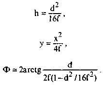
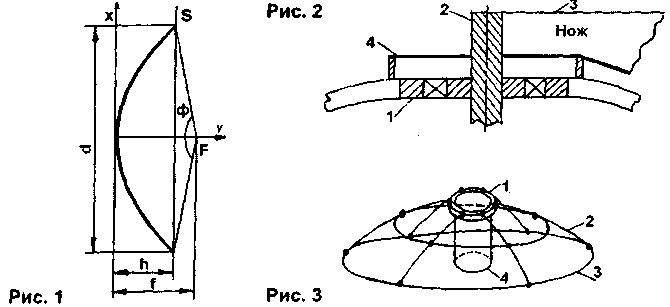
Encyclopedia of radio electronics and electrical engineering / Television antennas Having become interested in receiving STV, radio amateurs, as a rule, acquire a ready-made set of equipment for this. It usually includes a parabolic antenna (PA) of small diameter (0,9 ... 1,2 m). One of the first steps in upgrading the system is to purchase a larger diameter antenna. But large-diameter antennas are very expensive, so many people try to make PA at home. In the amateur radio literature, articles were published on the manufacture of PA, for example [1], but they did not take into account some factors. The fact is that when designing antennas, it is necessary to take into account the parameters of the feed, which is part of the converter. This article is aimed at systematizing data on the design of PA and applying them to the existing conditions. There are many types of microwave antennas - parabolic, phased arrays, based on Fresnel lenses, etc. With regard to home-made conditions, PA is recommended, due to the simplicity of their manufacture. There are two versions of the PA: - by gluing on the matrix; - soldering from copper wire and mesh (the so-called mesh antennas). Each antenna has its own advantages and disadvantages. The advantages of the first include the ease of control of the shape during manufacture, the second - less weight and windage. First of all, you need to determine which irradiator is available to the radio amateur. Let us turn to Fig. 1 and determine which parameters characterize the antenna. Firstly, this is its diameter d (as a rule, they are given at the beginning of the calculation). The shortest distance from the antenna focus (the converter feed is located at the focus, or the second mirror in the case of a two-reflector system) to the antenna reflector is called the focal length f. The mirror depth h is the greatest distance from the reflector opening plane S to the antenna reflector itself. The aperture angle Ф is the angle at which the aperture plane of the antenna mirror S is visible from its focus F. Moreover, they are related by the following relationships.
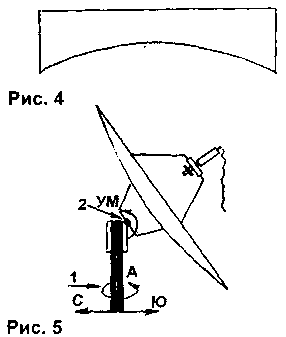
The f/d ratio determines the parameters of your illuminator. Usually f / d is in the range of 0,3 ... 0,5. The larger this ratio, the smaller h and the lower the consumption of materials for the manufacture of PA (with some loss of gain Ku). If you have an f/d=0,3 illuminator and want to keep your costs down, then purchase an f/d=0,5 illuminator, or a variable f/d illuminator is best. First, according to formula (2), the dependence of y on x (taking values from 0 to d / 2) is calculated and a table is compiled. The resulting values \u5b\u2bare transferred to graph paper and a parabola is built. Then it is glued onto a sheet of steel 2 mm thick and cut along the parabola line. Thus, a knife is obtained (it is necessary to strictly observe its shape, since the final result and the quality of the PA to a large extent depend on this). Then, in accordance with Fig. 1, you should select the rod 3 and bearing 2 of suitable dimensions (3 - knife). In this case, the knife is shortened by half the diameter of the rod 8 and welded to it coaxially. In accordance with Fig. 10, a frame is made of a steel bar with a diameter of 2 ... XNUMX mm (welding). In this case, the ribs XNUMX are approximately curved along the knife. A bearing is welded into the top of the frame. The frame is installed on a flat area, while under the bearing 1 (Fig. 3) it is necessary to vertically install a pipe 4 with an inner diameter greater than the diameter of the bearing 1. The entire space under the frame is filled with crushed stone or broken bricks. Having installed a washer 4 (Fig. 2) on the bearing with a diameter slightly larger than the bearing diameter and a height equal to the thickness of the future PA (for example, for a PA with a diameter of 2 m, the thickness is 25 mm), a knife is inserted into the bearing. The cement-sand concrete mortar is kneaded to a thick consistency, applied to the frame and leveled with a knife. The resulting matrix is dried for 3...5 days. On the third day (in dry weather), the resulting cracks are rubbed with alabaster and cleaned with sandpaper, controlling the quality of the surface with a knife. It should be noted that if you plan to use the matrix repeatedly, place two or three layers of roofing material between it and the ground so that it does not collapse from moisture. Also, I do not advise using the recommendation from [2] for making a clay matrix, because this material, when dried, gives many cracks, and the resulting matrix is short-lived. Next, proceed to gluing the antenna. There are many ways to carry out this process. Here are some tips. Firstly, if you are gluing a large diameter antenna, then remember the three disadvantages inherent in it - heavy weight, wind resistance and low strength. To simplify manufacturing, divide the antenna (exactly) into 6 ... 8 sectors (at the same time, take into account the shape of their connection, fastening). In this case, the matrix can also be made in the form of a sector, but it is still preferable to make it completely, because. it will be possible to glue offset antennas on it. For strength, increase the thickness of the reflector and reinforce it with radial steel wire ribs. As a material for gluing PA, they usually take fiberglass cut into strips and epoxy glue. You can use the technique described in [1], somewhat simplifying it. First, a release mixture is applied to the matrix washed with soap, which is used as automotive oil (the best result is obtained if the matrix is rubbed with an even layer of parquet mastic before this). A pipe is tightly inserted into washer 4 (Fig. 2), on which another washer made of duralumin is loosely put on, the height of which is equal to the thickness of the reflector. Next, a layer of resin is applied (without damaging the release mixture) and pieces of fiberglass are applied, smoothing them and removing air bubbles. Of course, it is desirable to use metallized fiberglass, but you can also use ordinary, due to the inaccessibility of the first. In the future (after manufacturing), it is necessary to paste over the reflector with pieces of aluminum foil cut out in a sector-like manner. Still, the first option, with reinforced fiberglass, is preferable because of the better surface quality. Another option for forming a conductive surface is to apply PA paints to the reflective surface, which include metal-powder bases (silver, etc.). Having brought the thickness of the reflector to the required dimensions, nuts are molded for its fastening. It is also possible to weld the frame to which the reflector is attached to the radial stiffeners with which the reflector is attached. The reflector can also be bolted through holes drilled into the PA after it has dried. Antennas of small diameter can be made from papier-mâché (the idea was suggested by R.K. Gaydinov). Newspapers are taken as a filler. They are soaked in water and passed through a meat grinder. Wallpaper paste is added to the resulting mass as a binder. The resulting mixture is applied to the matrix (having previously applied a separating mixture to it) and leveled with a spatula, forming the desired surface. After drying, the antenna is removed and covered with a conductive layer and several layers of nitro paint to protect the PA from atmospheric precipitation. Instead of newspapers, fabric can be used as described in [2], forming PA as in the case of fiberglass, using wallpaper paste as a binding material. The second version of PA (mesh) is described in [3]. A template is made for it (Fig. 4), the parameters of which are calculated by formula (2). Radial parabolas made of thick copper wire are bent along it. The thickness of the wire is selected based on the diameter of the antenna. For example, for an antenna with a diameter of 1,5 m, a wire with a diameter of 4 ... 5 mm is taken. It is also necessary to make circular belts. The diameter of the chords changes in increments of 10...30 cm. The places for soldering the chords to the radial parabolas are calculated by formula (1). After the frame is made, it is covered with a fine-mesh copper mesh, which is soldered to it. It should be noted that the larger the diameter of the PA, the thicker the wire from which it is made, and the more difficult it is to solder it (when using a wire with a diameter of more than 7 mm, contact welding is desirable).
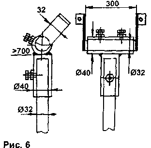
The next step is the manufacture of a slewing device (OPU). All OPUs are divided into two types: azimuth-elevation and polar. The first type is easier to manufacture, since it uses only two adjusting axes (both are used when reconfiguring from satellite to satellite). The first axis is azimuth, and its angle is calculated by the formula
where φ is the longitude of the receiving site in degrees, Fsz is the location of IC3 in orbit in degrees, w is the latitude of the receiving site in degrees. If you direct the antenna due south, then to tune to a given satellite in azimuth, you need to subtract 180 ° from A. If the angle is positive, the antenna is shifted by the value of this angle to the west; if negative - to the east. The elevation angle of the elevation axis 2 (Fig. 5) is calculated by the formula
The design of the suspension is arbitrary. Its dimensions depend on the diameter of the antenna. For example, for an antenna with a diameter of 1,2 m, the OPU is made in accordance with Fig. 6.
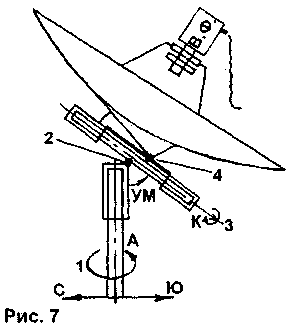
The specified type of OPA is mainly used with offset photodetectors and small-diameter direct focus photodetectors. Since large format antennas are heavier, it is inconvenient to realign them about two axes. Therefore, another type of OPU is used for them - polar (Fig. 7). It has four axes of rotation - A (1), UM (2), polar (3) and corrective (4). To orient the antenna, it is necessary that the plane to which the polar axis and the reflector axis belong lie in the plane of the azimuthal axis 1 and the direction to the south, marked at true noon. To determine the direction, a small pin is driven into the ground, and every 20 ... 30 minutes the position of the shadow cast by the pin is noted. The shortest distance from the end of the pin driven into the ground to the line traversed by the shadow of the end of the pin is the direction to the south.
Next, set the angle of the axis PA (2) equal to the latitude of the place of reception in degrees. Set the angle to the correction axis (4)
Then the polar axis (3) is rotated through an angle
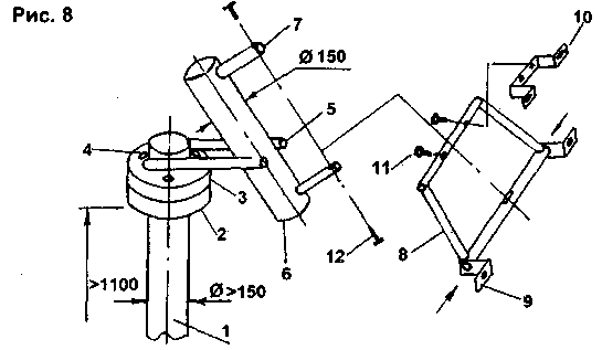
where f is the longitude of the place of reception; Fiss - location of the satellite in the GSO (if EL then (Piss>0, if west, then Fiss<0). As you can see, in the case of a polar suspension, only the polar axis is used to change from satellite to satellite (which gave the name to this type of OPU). Therefore, the retuning of the antenna is simplified. The tuning range lies within ±40° relative to the south direction. But for ease of use, they pay with the complication of the OPU mechanism. Figure 8 shows one of the many variants of the polar OPA.
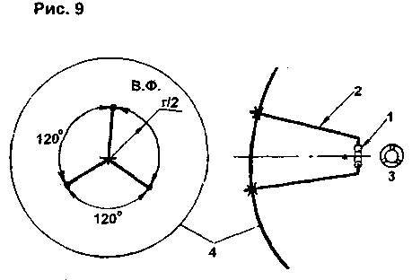
The dimensions are indicated for a PA with a diameter of 2 m. A flange 1 is welded to the pipe 2. A flange 3 is put on top, which freely rotates around its axis. The flanges have holes 4 for their mutual fixation. Two pipes 5 with a diameter of 40 mm and a length of 60 cm are welded to the upper flange. A pipe 6 80 cm long is attached to these pipes with two bolts. Two pipes 6 with a diameter of 7 mm and a length of 40 cm are welded to the pipe 25. A trapezoid 7 is attached to the pipes 8 by means of screws 12 (the trapezoid is made of pipes with a diameter of 25 ... 32 mm). An antenna reflector is attached to the trapezoid by means of brackets 9, 10 (very strong), while a pin with threaded ends is inserted into the lower tube of the trapezoid, and the bracket 10 is attached to the upper tube of the trapezoid by means of screws 11, which regulate the corrective angle. The elevation and polar axes are adjusted using lanyards (not shown in the figure for simplicity). It is important to arrange them in such a way that they are accessible and do not interfere with access to the converter, which has a retroreflective irradiator. I do not advise you to adapt all sorts of positioners, actuators and other means of remote adjustment, the use of which is justified only in cases where small-format PAs are used. In the manufacture of PA, it is necessary to ensure the minimum play of all joints, because Antenna turbulence in the wind has a bad effect on reception, and also leads to the rapid destruction of the OPA. To mount the converter to the antenna, in accordance with Fig. 9, three holes are drilled in the reflector. Ring 1 is made of duralumin with an inner diameter equal to the diameter of the converter neck. The ring can consist of two parts connected by bolts. Three holes 3 are drilled in the ring and threaded into them. Three rods 2 are made of duralumin (tubes). Their size is selected so that ring 1 is 2 ... 3 cm away from the focus point F. Threads are cut at the ends of the rods and screwed into ring 1, and then they are attached to reflector 4 .
The gain of the received antenna is calculated by the formula
where Q - surface utilization factor (KPI), for most types of irradiators Q = 0,4 ... 0,7 (usually 0,6); L is the length of the received wave. The table summarizes the data on Ku antennas of three diameters on the most used ranges (Q=0,6). As we can see, the higher the frequency, the larger the Ku of the antenna. But in the current situation (satellites have approximately equal effective radiated power) with different signal attenuation on the satellite-to-Earth path (at higher frequencies, the attenuation is greater), the resulting signal at the receiver input on different bands is approximately the same. Another interesting fact is that in the catalogs of many firms trading in PA, there are obviously overestimated Ku. You can check it yourself by calculating the KU using the above formula. Table 1
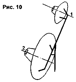
The table also shows that at low frequencies, the use of PA is impractical due to the lower Ku in comparison with antenna phased arrays. I'll give you a few tips. 1. The larger the diameter of the PA, the narrower its radiation pattern, so it is advisable to install a small diameter antenna next to a large antenna and tune it to a satellite that has the maximum signal level in your area. Then, noticing the approximate direction to the satellite, point the large antenna in the same direction. After receiving the signal, correct the position of the irradiator in the focus of the antenna for the best image reception of weak channels. It is possible to simplify the reconfiguration of the large antenna even more by fixing the small one on its edge in such a way that the axes of rotation of the PA 1, 2 (Fig. 10) are parallel. It is necessary to introduce corrective screws into the mounting scheme of a small antenna to pre-set the parallelism of the antenna axes. Having received the signal with a small antenna, they switch to a large one.
For fine tuning to a satellite (even with a very small signal), it is very convenient to use special detectors, the circuits of which were published in amateur radio literature. Also, for this purpose, you can use a spectrum analyzer (in the range from 1 to 2 GHz), applying a signal from the converter through an isolation capacitor. In this case, do not forget to apply a +14 V supply voltage to the converter. 2. It is necessary to carefully ground the antenna and the converter in order to avoid failure of the equipment during a thunderstorm (judging by the statistics, this happens quite often). To do this, wind on the connector connecting the cable to the converter, 2 ... 3 turns of wire with a diameter of 1,5 ... 2 mm and ground it. The same wire is used to ground (separately and in parallel to one circuit) the metal surface of the antenna and the OPU. 3. Do not forget that the larger the diameter of the antenna, the greater its wind resistance, so it is necessary to provide measures to protect the antenna and the OPU from wind loads. Use high-quality rolled steel for the manufacture of OPU. For example, if a meter-long PA requires a carrier pipe with a diameter of 32 ... 40 mm, then for a two-meter one - 120 ... 150 mm. If possible, install the antenna so that it is protected from the back by a wall. If possible, avoid mounting the antenna at a height. In conclusion, I want to note that this article describes only a small part of antenna systems. I personally thank V.V. Orlov and S.A. Kozlov for their help in the manufacture of metal structures, the drawings of which are given in this article. Literature
Author: V. Fedorov, pgg. Leo Tolstoy, Lipetsk region; Publication: N. Bolshakov, rf.atnn.ru
Artificial leather for touch emulation
15.04.2024 Petgugu Global cat litter
15.04.2024 The attractiveness of caring men
14.04.2024
▪ New technology for 3D printing complex objects based on cellulose ▪ Treatment of diabetes with insulin cell transplantation
▪ section of the site Encyclopedia of radio electronics and electrical engineering. Article selection ▪ article And you are passionate, Paramosha! Popular expression ▪ Phytolacca American article. Legends, cultivation, methods of application ▪ article Jewel from the magazine. Focus Secret
Home page | Library | Articles | Website map | Site Reviews www.diagram.com.ua |


 Arabic
 Bengali
 Chinese
 English
 French
 German
 Hebrew
 Hindi
Hindi Italian
 Japanese
 Korean
 Malay
Malay Polish
 Portuguese
 Spanish
 Turkish
 Ukrainian
 Vietnamese



 Leave your comment on this article: