|
|


 Arabic
 Bengali
 Chinese
 English
 French
 German
 Hebrew
 Hindi
Hindi Italian
 Japanese
 Korean
 Malay
Malay Polish
 Portuguese
 Spanish
 Turkish
 Ukrainian
 Vietnamese
|
ENCYCLOPEDIA OF RADIO ELECTRONICS AND ELECTRICAL ENGINEERING Let's talk about antennas?. Encyclopedia of radio electronics and electrical engineering
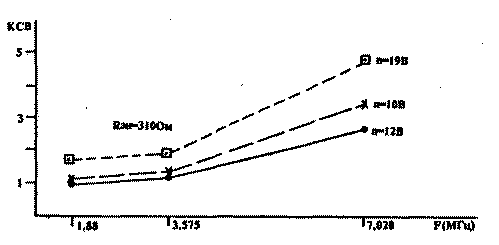
Encyclopedia of radio electronics and electrical engineering / Antennas. Theory It is known that the capabilities of the most advanced transceiver cannot be realized without the use of highly efficient antenna-feeder systems (AFS), which include a complex of devices from the transmitter output to antennas. We will consider some general issues of creating an AFS, dwelling in more detail on the design of a broadband transformer (SHPT). Practice shows that the broadband of the SPT allows to achieve satisfactory results of their work in the entire range, but does not guarantee the maximum use of the capabilities of the APS. This situation can be explained by the insufficient knowledge by radio amateurs of the degree of influence of the design of the APS on the efficiency of the system. 1. FIELD OF APPLICATION Most SPTs are designed to operate in all HF bands: from 1,8 MHz to 28 MHz inclusive. If we take into account the difference in the mechanisms of energy transmission by transformers of low and high frequencies, then with the use of the WPT in a wide range, we can agree with [1]. We share the point of view, unfortunately, of a foreign author unknown to us, set forth in the article "A New Class of Transformers on Coaxial Lines"; From the analysis of the practice of using SPT, the author draws the following conclusions: - ShPT is advisable to use only when working with low power and only in the low-frequency sections of the HF bands; - the disadvantages of WPTs include the non-linearity of their characteristics when the core is saturated, leading to signal distortion, as well as the danger of an arc discharge when operating at high power, which can lead to the destruction of the core. On our own behalf, we add that we do not exclude the fundamental possibility of creating a SPT with good performance in the high-frequency HF bands. Apparently, it is more correct to talk about limiting the frequency spectrum of the WPT to two or three adjacent ranges, within which the transformer has satisfactory performance. 2. WINDING MATERIAL Domestic authors recommend using enameled wires or stranded installation wire in PVC insulation for the windings of the SHPT [2]. 3. DESIGN OF WINDINGS The windings of a transformer with K = 1: 4 are wound with a double-folded wire. In our opinion, the frequency response of the SPT can be corrected by changing the design of the windings and the number of turns in them. 4. APS SETUP The highest indicators of APS are achieved with precise coordination of all elements of the system, i.e. when the impedances of the mating stages are either equal or matched using special devices. The components of the impedance - capacitive and inductive - change according to different laws with a change in frequency, and therefore it is impossible to achieve complete coordination of the system elements in a wide frequency range. Setting up the APS practically comes down to such a selection of the design of the system elements, which achieves either fairly uniform and relatively high performance of its operation in all ranges, or the highest performance in a pre-planned frequency range. The degree of adjustment of the APS is judged by the SWR values. 5. SWR SWR is the most important indicator by which, with a certain degree of certainty, one can judge the actual effectiveness of the drug substance. Almost all shortwaves know that when setting up the AFS, one should strive for the coveted "one" and not "go beyond" some boundary SWR values. But at the same time, not everyone delve into the physical essence of the indicator, which is the ratio of the largest of the total resistances of the mating elements to the smallest. Note that it is impossible to determine from the SWR values which of the mating resistances has a large value. For example, if the transmitter is perfectly matched to the 75 ohm feeder and the SWR is -3,0, then the input impedance of the antenna connected directly to the feeder can be either 25 ohms or 225 ohms. With such a wide range of possible values, the order of magnitude of the resistance is easily determined from the literature data. The actual value of the antenna impedance can be measured by instruments [3]. As already noted, for radio amateurs, it is not the magnitude of the antenna resistance that is of greater interest, but the identification of the dependence of the system efficiency on the design of its elements. Achieving the minimum SWR values indicates the fulfillment of the task. When talking about the APS tuning, we assumed that the transmitter was precisely tuned to the calculated load impedance. However, as practice shows, this setting is not always given due attention, resulting in reduced radiated power. We offer a simple method for setting up the transmitter in the operating mode. It is necessary to connect a non-inductive dummy load to the transmitter output through an SWR meter and, by adjusting the cascade, including the selection of inductances, achieve SWR-1,0. (Note that we consider the widespread practice of using various incandescent lamps as a load equivalent to be erroneous, since the lamp does not have a purely active resistance.) It was noted above that it is possible to judge the effectiveness of an APS based on the readings of an SWR meter only with a certain degree of reliability, which depends both on the design of the APS and on the location of the SWR meter in it [5]. As a rule, the device is located at the output of the transmitter, which is convenient from a practical point of view. The highest reliability of the estimate will correspond to the case of direct connection of the antenna to the feeder, the lowest - in the presence of a matching device (CS). The achievement of the minimum SWR values in the presence of SU indicates the tuning of the APS to a given frequency, but does not characterize the degree of transmission of the transmitter energy to the antenna. In order to accurately match all elements of the APS containing the control system, in the process of setting up the system, it is necessary to simultaneously measure the SWR both before the control system and after it. Despite the complexity of the practical implementation of measurements, they are of undoubted interest. At the same time, the remark about measuring the SWR in the line from the control system to the antenna can rather be classified as a wish, because SWR meters used by radio amateurs are not designed to work in high-impedance transmission lines. But there is a compromise solution. The degree of coordination of the control system with the antenna can be judged by the maximum values of the antenna current measured by the non-inductive method. In order to eliminate errors that can be caused by parasitic antenna resonances, current curves should be considered in conjunction with the frequency response of the antenna. The design of the SPT [2] recommended by the author was intended for operation with an antenna having an input impedance of 300 ohms, operating in the ranges of 1,8 ... 28 MHz. Recommended value n=8...15 turns. For windings, wires in enamel insulation or stranded installation wire in PVC insulation are recommended. We have used: core fuel assembly, wire - PE 1,0. The SPT input was connected to the RF generator using a 75 ohm feeder 18 m long through an SWR meter. Load equivalents RSH with a resistance of 75, 155, 310, 420, 500 and 600 Ohm were connected in turn to the transformer output. The degree of coordination of the input of the SHPT with the generator was estimated by the values of the SWR. Initial experiments, carried out in a wide frequency spectrum (Table 1), determined the possible scope of the WPT. Table 1. SWR in the feeder at different values of the operating frequency (F) and the number of turns (9) ShPT (Resistance of the equivalent load Ren = 310 Ohm)
Subsequent experiments (Table 2, Fig. 1) were carried out at medium frequencies of 160, 80 and 40-meter ranges, in which it was supposed to work on the air. Table 2. SWR in the feeder at various values of the operating frequency (F), the number of turns (n) wt and the resistance of the equivalent load (Ren)
Based on the experimental results, one can following conclusions about the tested FSPs.
Summarizing the above, we will try to formulate some recommendations for the creation and configuration of multi-range APS using the FFS.
Bringing the results of the experiments carried out to the attention of readers, we consider them only as informational material, and not as a description of the design to be repeated. The purpose of the article is to draw attention to the problems of creating highly efficient APS, to encourage radio amateurs to experiment, to exchange experience. Literature 1. S.G. Bunin, L.P. Yaylenko. Handbook of a radio amateur-shortwave. 2nd edition. Kyiv. "Technique". 1984
Authors: V. Panteleev (UA3TX), D. Panteleev (UA3TJW); Publication: N. Bolshakov, rf.atnn.ru
Artificial leather for touch emulation
15.04.2024 Petgugu Global cat litter
15.04.2024 The attractiveness of caring men
14.04.2024
▪ Mobile Internet is more popular than voice communication ▪ Germanan is a rival of graphene ▪ An artificial nerve cell has been created ▪ Processing moon dust into oxygen
▪ section of the site Spy stuff. Article selection ▪ article Art for art's sake. Popular expression ▪ article Head of the expedition. Job description ▪ article Colored lights. Focus Secret
Home page | Library | Articles | Website map | Site Reviews
www.diagram.com.ua | ||||||||||||||||||||||||||||||||||||||||||||||||||||||||||||||||||||||||||||||||||||||||||||||||||||||||||||||||||||||||||||||||||||||||||||

 Leave your comment on this article: