|
|


 Arabic
 Bengali
 Chinese
 English
 French
 German
 Hebrew
 Hindi
Hindi Italian
 Japanese
 Korean
 Malay
Malay Polish
 Portuguese
 Spanish
 Turkish
 Ukrainian
 Vietnamese
|
ENCYCLOPEDIA OF RADIO ELECTRONICS AND ELECTRICAL ENGINEERING All-wave antenna D2T. Encyclopedia of radio electronics and electrical engineering
Encyclopedia of radio electronics and electrical engineering / HF antennas We bring to the attention of readers a description of the design of the antenna, operating on all amateur bands. In the review "Three KB antennas" ("Radio", 2000, No. 4, pp. 62-64), it was noted that T2FD type antennas containing resistors in the emitter sheet can be used at frequencies below and above the optimum for which they are designed. An advertisement for a D2T antenna has recently appeared in amateur radio magazines and the Internet. It, according to its manufacturer, WiMo, operates in the frequency band from 1,5 to 200 MHz. Since the antenna is mass-produced, it has been studied quite well. The results of these studies are of interest to anyone who decides to make an antenna with a resistor in the emitter sheet. Antenna D2T (Andreas Splanemann, "D2T - alle Bander mit einer Antenne?", 2000, No. 2, S. 116-119) consists of two loop vibrators spaced horizontally with active power and with a resistor in the canvas of one of them (Fig. 1). The loop vibrators are 6 m long, and the distance between the sides of the loop is about 0,15 m. The distance between the vibrators is 2 m. The antenna is powered by a coaxial cable with a wave impedance of 50 ohms through a matching balun transformer with a resistance transformation ratio of 1:9. Load resistor resistance - 820 Ohm.
According to the manufacturer's data, SWR within all amateur KB bands and on the 144 MHz band does not exceed 2. Radio amateurs who reproduced this antenna received different SWR results. For almost everyone, it really was basically less than 2, and only for individual radio amateurs on some amateur bands, the SWR was within 2 ... 3. Discrepancies with the data of the firm can be explained by local conditions (for example, due to the influence of the “iron” surrounding the antenna that cannot be taken into account).
The radiation patterns for the D2T antenna in the horizontal and vertical planes (range 14 MHz) are shown in fig. 2 and 3, respectively. On this band (as well as on other high-frequency KB bands), the radiation pattern in the horizontal plane has certain directional properties. The ratio of emissions back/forward, however, is small (a few decibels), but the ratio of emissions forward/sideways reaches 10 dB or more. The latter allows the D2T to be used on these bands as a rotating directional antenna (for interference mitigation). On the 14 MHz band, D2T in the direction of the radiation maximum is slightly inferior to the dipole (-1 dB), and on the 28 MHz band it noticeably exceeds it (+6 dB).
On low-frequency ranges (7 MHz and below), the antenna pattern in the horizontal plane is almost circular, and in the vertical - the radiation maximum begins to shift towards the zenith. On the 7 MHz band, D2T is already 6,5 dB inferior to the dipole, which, taking into account the dimensions of the antenna, can be considered an acceptable value. On the 144 MHz band, the antenna pattern resembles a "chamomile" with several dips up to 10 ... 15 dB in relation to the maximum radiation.
The design of the D2T antenna is simple. It consists of a bearing traverse (BOOM) 2 m long, at the ends of which dielectric pipes 3 m long are fixed (Fig. 4). They serve as the basis for the wire loops that form the emitter. To support the tops of the loops, each element has three dielectric posts - one in the center (Fig. 4) and one at the end of each dielectric tube (Fig. 5). To these pipes and to vertical posts, the wire of the antenna web is attached with bandages made of insulating tape.
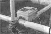
The central posts have in the upper part dielectric crossbars about 0,1 m long (Fig. 6), which fix the wires that form the upper parts of the radiators, and the wires of the line connecting the loop vibrators.
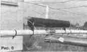
The matching-balancing transformer is placed in a moisture-proof housing, which is mounted on a carrier traverse (see Fig. 4). The resistor is placed in a segment of a dielectric pipe 0,3 m long and mounted on dielectric pipes supporting the lower wire of the corresponding loop (Fig. 6). According to the company, in the "Press" mode for different frequency bands, the following power can be supplied to the antenna: 100 W - 1,5 ... 2,5 MHz, 200 W - 2,5 ... 4 MHz, 400 W - 4. ..10 MHz, 500 W - 10...30 MHz, 200 W - VHF bands. Since at low frequencies most of the power supplied to the antenna is dissipated in this resistor, it can be assumed that the load resistor should have a power dissipation of 100 watts. It should be noted that the ratio of the power dissipation of the resistor and the allowable power of the transmitter in the main operating frequency band for the D2T antenna is about 0,2. This parameter is better for her than for T2FD, for which it is usually recommended to choose about 0,3. Author: Andreas Splanemann; Publication: N. Bolshakov, rf.atnn.ru
Machine for thinning flowers in gardens
02.05.2024 Advanced Infrared Microscope
02.05.2024 Air trap for insects
01.05.2024
▪ Long memory of the Australian aborigines ▪ A new device for radio-controlled aircraft and helicopters
▪ section of the site Experiments in chemistry. Article selection ▪ Primus article. History of invention and production ▪ article Where and when did a spontaneous natural nuclear reactor operate? Detailed answer ▪ Bulldozer driver article. Standard instruction on labor protection
Home page | Library | Articles | Website map | Site Reviews
www.diagram.com.ua |


 Leave your comment on this article: