|
|


 Arabic
 Bengali
 Chinese
 English
 French
 German
 Hebrew
 Hindi
Hindi Italian
 Japanese
 Korean
 Malay
Malay Polish
 Portuguese
 Spanish
 Turkish
 Ukrainian
 Vietnamese
|
ENCYCLOPEDIA OF RADIO ELECTRONICS AND ELECTRICAL ENGINEERING High performance antennas at 430 MHz. Encyclopedia of radio electronics and electrical engineering
Encyclopedia of radio electronics and electrical engineering / VHF antennas In the decimeter wave range (DCW), it is recommended to use high-performance antennas with a sharp radiation pattern for the following reasons. The high directivity of the antennas significantly increases the energy potential of the communication line, which allows either to increase the communication range or reduce the transmitter power. The latter is beneficial not only economically, but also because it is difficult to obtain high transmitter powers in the DCV range. In addition, with a high directivity of the antennas, the possibility of exposure to the receiving device of extraneous interference is reduced. Finally, highly directional antennas make it possible to reduce the mutual influence of several closely spaced communication systems operating in the same frequency range. Antenna gain directly related to its directional properties, c. to a certain extent compensates for the loss of RF energy during propagation along the communication line. As the distance between correspondents increases, the level of the transmitted signal decreases and it becomes necessary to use more and more directional antennas. Such antennas can be built by combining several antennas with relatively weak directivity into a system (array). Single antennas included in the array should be located relative to each other at optimal distances, taking into account their directional properties. At distances less than optimal, the antennas in the array will be underused and the directivity factor (DRC) of the array will be less than possible. Distances greater than optimal are impractical, since in this case the dimensions of the antenna device as a whole unreasonably increase and its directivity characteristic worsens (the main lobe narrows and the side lobe grows). Approximately choose the distance between the individual array antennas, using the concept of the effective surface Seff of a single antenna with directivity = Do. Seff=(Dol2)/4p; where l is the wavelength. Representing conditionally this surface as a square with side a=l/2Sqr(Do/p), it is possible to place the electrical centers of the antennas in the array along the vertices of the square with side "a". In this case, the effective surface Speff antenna array will be approximately equal to n * Seff, where n is the number of antennas included in the array. It is obvious that the value of the gain of an antenna array depends both on the value of Do (the gain of each single antenna) and on the number of single antennas forming the array. With an increase in this number, technical difficulties increase in the common-mode power supply of the array antennas and in matching it with the feeder. Reducing the operating wavelength exacerbates these difficulties, and in the considered frequency range they are already quite noticeable. An essential point in the construction of a multi-element antenna array is the choice of its element - a single antenna. This element should be structurally simple and have aperiodic properties. The latter quality is especially necessary when making an antenna array in amateur conditions, when it is difficult to make a large number of single antennas with high identity. The absence of pronounced resonant properties in a single antenna makes it possible, without much damage to the array as a whole, to allow deviations from the specified dimensions when making antenna parts. A zigzag emitter shown in Fig. 1 can be used as such an element. This figure shows the dimensions of the radiator for the frequency range 430-440 MHz.
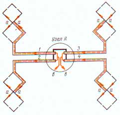
The emitter is made of eight solid identical metal plates fastened together in any way (soldering, bolts or rivets). When fastening with bolts or rivets at the feed points of the antenna a - a, it is necessary to install tinned brass petals for soldering the feeder. With this design of the emitter, at its points b-b there will be current antinodes and, accordingly, zero voltages. Due to this, the emitter can be fixed with metal racks to the reflector by points b-b, and a distribution feeder can be passed through one of these points without violating the electrical symmetry of the antenna. Thus, there is no need to manufacture and use any special balancing device. The distribution feeder from point "b", which has a zero potential, is laid along two plates of the emitter to its power points, where it is soldered to it. To make the emitter stronger, a dielectric board can be placed between points a-a. The simple design of the emitter allows its multiple production with high identity. The directivity factor and the TWV (traveling wave coefficient) of this radiator weakly depend on the frequency, and practically do not change in the operating wavelength range. Thus, the design of the radiator and its aperiodic properties satisfy the requirements for an antenna array element. The next step in building an antenna array is the placement of elements in the array and the choice of distances between them. The radiation patterns in the E and H planes of polarization of a zigzag radiator with a reflector in a given wave range are almost the same. This allows one to place the elements of the lattice along the vertices of a square with a side approximately equal to 0.9l. For successful operation of the antenna array, it is necessary to properly feed it and coordinate the elements of the array with the main feeder. In this case, it is desirable that the power supply system ensures the in-phase radiation of the array elements and the equality of the powers supplied to them. The principle of operation of the power supply system used in the described antenna array can be understood from Fig.2.
This figure shows four zigzag radiators, the conductors of which are excited in phase from the feed points in-in. In this case, distribution feeders 1 and 2, 3 and 4 are connected in pairs in parallel, and the pairs themselves at the points in-in are connected in series. This allows, in the first approximation, at points c-c to restore the values of the input resistances available at the input of each individual distribution feeder and thereby ensure the same degree of matching of the feeder supplying four emitters as the feeder supplying one emitter (KBV ~ 0,6 -0,7). The phases of the voltage supplied to the power points of the I-V are shifted relative to each other by 180 °, therefore, for the correct phasing of the emitters, it is necessary to artificially create an additional phase shift by 180 °. This shift can be carried out by laying, for example, distribution feeders 1 and 3 on the right sides of the radiators, and feeders 3 and 4 - respectively on the left. Naturally, the electrical lengths of the distribution cables from the feed points in-c to the feed points of the emitters aa must be the same. On fig. 3a shows the structural implementation of the installation of coaxial cables of four distribution feeders in node A.
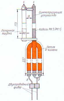
The cable connections at node A are very simple and need no further explanation. It should only be borne in mind that the lengths of the connecting conductors should be as small as possible, and the soldering points should be extremely accurate. Node A is mounted on a dielectric board, which must be moved 40-50 mm away from the mast. As the main feeder for the four emitters, you can take either a 75-ohm coaxial cable (preferably RK-3) or a 300-ohm two-wire line. In the first case, the cable must be connected to the power points c - c through a balancing device, a general view of which is shown in Fig. 3,b.
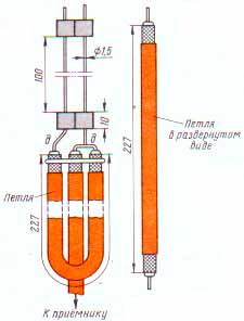
This device consists of two conductors of equal diameter, shorted together at a distance of 173 mm from the point of connection of the center conductor of the cable. The role of one of the conductors of the balancing device is performed by the shielding braid of the main feeder, and a brass tube is used as the other. With points g-d, the balancing device is connected to the points v-v of node A. The conductors of the balancing device must be fixed to the dielectric power board of node A so that mechanical forces from the feeder are not transmitted to the excitation points v - c and do not break contact in them. When a two-wire line with a wave impedance of 300 ohms is used as the main feeder, another U-elbow is connected to the balancing device (in Fig. 3, b below). With a feeder made of cable RK-3 or RK-1, it is not necessary to turn on the U-elbow. The U-elbow quadruples the resistance values, providing both the necessary resistance transformation in case of using a two-wire line, and balancing. A two-wire line with a wave impedance of 300 ohms can be made of copper wire. To fix the wires of the line, posts should be fixed on them, cut from the polyethylene insulation of the PK-3 cable into small pieces about 10 mm long. Pieces of insulation put on the wires of the line are fastened together in pairs with an insulating tape (Fig. 4).
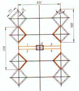
Before entering the house, the end of the two-wire line should be connected at points e-d to another ET-elbow, as shown in Fig. 4. The device and dimensions of the antenna array of four radiators, the scheme of which is shown in Fig. 2, are shown in Fig. 5.
The directivity factor of this grating is about 40. The design of the frame on which the emitters are located is shown in Fig.6. It consists of four horizontal and two vertical rails mounted on the mast.
If the emitters are made of sufficiently rigid materials, vertical slats can be omitted. To increase the directivity of the antenna array, it is advisable to use a reflector. One of the reflector options is shown in Fig.7.
It consists of two horizontal rails, along the edges of which two segments of an antenna cord or bare copper wire with a diameter of 2-3 mm are fixed. Transverse conductors with a diameter of 0,5-1 mm are attached to the antenna cords (or wires), which form the wall of the reflector. The reflector is mounted on the mast using two brackets (Fig. 7). It should be as light as possible. A general view of the array of four emitters with a reflector is shown in Fig. 8.
When installing the grating, you should accurately direct it to the correspondent. The guy wires of the mast should not cross and even more so touch the conductors of the radiators of the antenna array. If the guys run in front of the antenna web, then they must consist of several parts with insulators between them. The distance between the insulators should be about 150 mm. The wires of the two-wire line may run parallel to the mast, but must not touch it. In places of inflection, they can be fixed on insulators. However, it is necessary to strive to ensure that the conductors of a two-wire line during fastening and bending (preferably smoother) are not strongly deformed. So, for example, they cannot be wrapped around insulators, as is done with the wires of the lighting network. As can be seen from the figures, the dimensions of the antenna array of four emitters are relatively small. It is possible to increase the directivity factor of the grating up to about 150-160 by further quadrupling it. The selected power supply scheme for the lattice elements allows this to be done without much difficulty. Figure 9 shows the feeding scheme of an antenna array of 16 elements. It is similar to the diagram in Fig. 2, if we consider each four emitters as a single element. All nodes in Fig. 9 with feed points in-in and in'-in' are performed as shown in race 3. Both a 75-ohm coaxial cable with a balun and a two-wire 300-ohm line using a ST elbow can be connected to the B'-B' points as the main feeder. The installation of power lines requires special attention, since improper connection of the ends of the balancing device in any of the power nodes will cause the entire antenna array to be out of phase. The layout of distribution cables to the power points of the zigzag radiators themselves in quadruples is also shown in Fig. 9.
You can mount a grid of 16 emitters on the frame as shown in Fig.10. Here, too, vertical slats are not always needed. The antenna reflector is made in the manner described above.
The requirements for the implementation of the feeder system are fully preserved. The requirements for the thoroughness of the system adjustment and its mechanical rigidity are increasing. The antenna has a relatively high directivity. The opening angle of its radiation patterns at half power level is about 16°. Consequently, deviations from the direction to the correspondent and in elevation exceeding ±4° are undesirable. Author: K. Kharchenko; Publication: N. Bolshakov, rf.atnn.ru
The world's tallest astronomical observatory opened
04.05.2024 Controlling objects using air currents
04.05.2024 Purebred dogs get sick no more often than purebred dogs
03.05.2024
▪ LibreSync LS9 Wireless Module ▪ SAMSUNG and LG mobile phones will harm mobile operators ▪ Electronics will assess the tone of the computer user ▪ If aliens exist, we will know about them in the next 20 years
▪ site section Indicators, sensors, detectors. Article selection ▪ article by Bernard Le Bovier de Fontenelle. Famous aphorisms ▪ article Why do the number of days in months differ? Detailed answer ▪ article Piston cleaner. home workshop ▪ article PWM fan speed controller. Encyclopedia of radio electronics and electrical engineering
Home page | Library | Articles | Website map | Site Reviews
www.diagram.com.ua |


 Leave your comment on this article: