|
|


 Arabic
 Bengali
 Chinese
 English
 French
 German
 Hebrew
 Hindi
Hindi Italian
 Japanese
 Korean
 Malay
Malay Polish
 Portuguese
 Spanish
 Turkish
 Ukrainian
 Vietnamese
|
ENCYCLOPEDIA OF RADIO ELECTRONICS AND ELECTRICAL ENGINEERING Expanding the capabilities of the ALAN-48+ radio station. Encyclopedia of radio electronics and electrical engineering
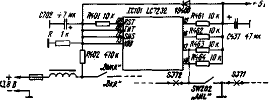
Encyclopedia of radio electronics and electrical engineering / Civil radio communications Many users of the CBS band (27 MHz) have at their disposal car-base radio stations "ALAN-48+". Their functionality can be expanded by installing additional buttons and connecting them to certain processor pins. The ALAN-48+ radio station has good service capabilities, such as channel-by-channel scanning, memory for five frequency channels, prompt switching to the emergency channel - the 9th channel of the "D" grid (the "D" grid in this radio station corresponds to the "C" grid "according to common notation). As in all modern radio communication equipment, the synthesis of the frequencies of the receiver's local oscillator and the transmitter's master oscillator. switching the radio station to various modes and types of work, displaying information on the liquid crystal display are carried out by a microprocessor. which replaces several blocks of radio stations of previous generations. "ALAN-48+" uses LC7232 microprocessor. However, not all functions supported by it are implemented in a serial device. The author of these lines could not find any literature on foreign microprocessors for such radio stations. Probably, the necessary information can be found only in the catalogs of manufacturers, which. unfortunately, it is almost impossible to get it in our country. Therefore, it was necessary to conduct an experimental study of some functions of the microprocessor. The results of the experiments are summarized in table. 1. The conventional names of the microprocessor pins are indicated horizontally and vertically according to the schematic diagram included in the delivery set, and their serial numbers are in brackets. The purpose of these pins is to poll the keyboard. or. as it is sometimes said, the keyboard scan. The poll proceeds as follows. The microprocessor alternately sends short pulses to the outputs T1-T5. When one of the keys is closed, the pulses from the corresponding output are fed to one of the inputs K10-K13. As a result, the microprocessor "determines". which of the keys is pressed and issues a command to enable / disable the corresponding function. They are listed in Table. 1. The functions already implemented by the manufacturer in the serial version "ALAN-48+" are highlighted in color. By installing additional buttons (non-latching) in the radio station, which could close two outputs of the microprocessor, in accordance with Table. 1, you can enter additional functions that are not provided in the factory version, but supported by the microprocessor. The most useful will be the introduction of the scan function for channels stored in memory. To do this, it is necessary to install an additional button on the front panel of the radio station and turn it on so that when pressed, the input K 11 of the microprocessor closes with the output T5 (pins 34 and 26). To use this function, the numbers of the frequency channels of interest must be entered into the memory cells M1-M5. Then - click on the installed button. On the liquid crystal display (LCD) of the radio station will appear the inscription "M. SCAN", and in the lower part of the inscription "Ml". Table 1
Note. LOW - switching from the full output power mode of the transmitter to the low power mode and vice versa; AM / FM - switching the type of modulation - AM / FM; CH 9, CH 19 - switching to emergency channels (EMG); M1...M5 - switching to channels recorded in the corresponding memory cells, as well as writing to these cells; CH. DOWN, CH. UP - switching the radio station one channel down and up, respectively; SCAN - enable/disable per-channel scanning; M. SCAN - enable/disable scanning for channels stored in memory; SAVE - enable/disable battery saving mode; LOCK - lock the keyboard from accidental keystrokes. "M2",..., "M5" will quickly replace each other. At this time, the radio cycles through the channels stored in the memory. This will continue until a signal appears in one of the channels, the level of which exceeds the squelch threshold (similar to the "SCAN" channel-by-channel scanning function). Thus, any five pre-selected frequency channels can be monitored simultaneously. If you need to listen to less than five channels, then you will need to re-enter the numbers at once into two or three non-adjacent memory cells "Ml" - "M5". If you have to conduct a radio exchange not only with remote correspondents, but also with those who are at a short distance, it is useful to enter into the radio station a mode of reduced transmitter output power. To do this, you need to install another button on the front panel of the radio station and turn it on so that when pressed, the input K 12 of the microprocessor closes with the output T1 (pins 33 and 30). The missing diode D113 is installed on the main printed circuit board of the radio station (there is a place for it and holes on the board). Any silicon diode with a maximum allowable forward current of at least 300 mA will do. Switching from full to low power and back will be done by pressing this new button. According to the measurements made by the author, the output power of the transmitter in the reduced power mode is approximately 800 mW. Which mode is enabled - full power or reduced - can be determined by the output power indicator on the LCD during transmission. It will become more convenient to use the station if a resistor with a resistance of 59 kOhm is installed between pin 20 of the microprocessor and pin 750 of the LCD. Then, when operating in the low power mode, the LCD will display the inscription "LOW", and in the full power mode this inscription will not appear. However, due to the high density of mounting, it is not so easy to do it carefully, without having the appropriate experience. You will need a magnifying glass with at least three times magnification and a soldering iron with a sharply sharpened tip. Since the distance between the pins of the microprocessor is very small, when introducing all additional functions into the radio station, it is more convenient to solder the mounting wires not to the pins of the microprocessor directly, but to the conductors of the keyboard printed circuit board, which have an electrical connection with these pins. It is convenient to use imported miniature buttons. It is best to install them on the front panel of the device below the "AM / FM" and "SCAN" keys. All of the above improvements can be carried out without having a circuit diagram of the radio station itself, using the materials of this article. According to the same principle, it is permissible to refine other radio stations with microprocessors. Almost always, the microprocessor has more functions than the radio itself performs. It's just that the manufacturer, for various reasons, did not consider it necessary to install extra, from his point of view, keys on the front panel. The search for additional functions can be carried out by briefly shorting the microprocessor outputs serving the keyboard in different combinations. Note that such short circuits are the operating mode of the microprocessor and one should not be afraid for its failure. As you know, the CBS frequency grid in the Russian standard is shifted down by 5 kHz relative to the frequency grid adopted in most countries of the world. In previous publications of the magazine, methods were proposed for converting imported radio stations to work in the Russian frequency grid by slightly shifting the frequency at which the crystal oscillator operates, synchronizing the operation of the microprocessor. However, in modern radio stations, this can be done much more easily and without compromising frequency stability. In the LC7232 microprocessor of the ALAN-48+ radio station, pins 15 to 18 are used to set the microprocessor operation mode at startup. Immediately after power is supplied to the radio, the microprocessor polls these pins. Each of them can have either a logical zero (the output is connected to a common wire), or a logical unit (a voltage of 10 V is supplied to the output through a resistor with a resistance of about 5 kOhm). Depending on the state of these four inputs, the microprocessor starts to work according to one of the 16 programs embedded in it. Different programs correspond to different operating frequency ranges of the radio station, different channel numbering systems, and may or may not allow you to work with AM or FM in different parts of the band.
Status polling occurs only when the processor is initialized (when the power is turned on). Similar conclusions are available in other microprocessors. With these pins, as well as with the pins serving the keyboard, the reader can safely experiment without fear that the processor will fail. At the same time, one should not forget that the levels at these inputs affect the operation of the microprocessor only when it is started. Table 2
Note. CH/F - indication switching (channel number or frequency); DW - switching to the dual reception mode - alternate reception on two frequencies (channels); LIGHT - turn on the backlight of the display; BAND - switching frequency grids. Other functions - as in the table. one. For radio amateurs and CB users in "ALAN-48+" two states are of interest: "1111" and "1100" for the microprocessor pins from the 15th to the 18th, respectively. "1111" - factory version. "1100" differs from the state "1111" only in that the entire working frequency grid of the radio station is shifted down by 5 kHz, i.e. the radio station begins to operate in the Russian frequency standard. In order for the radio station to work not only in the European, but also in the Russian frequency standard, it is necessary to refine it according to the figure (changes are shown in red). Resistor R is used to discharge the capacitor C702 after turning off the power to reset the previous state of the microprocessor. To switch modes "Europe / Russia" it is advisable to use the switch SW202 "ANL", which in the factory version serves to turn on the filter of impulse noise. Then, as a result of refinement, this filter will be permanently enabled. In practice, this does not cause any inconvenience in work. SJ71 and SJ72 are PCB jumpers that need to be cut to disconnect switch SW202 from the radio's circuits. To select the desired frequency standard, you must first set SW202 to the appropriate position, and then turn the radio off and on again. It is possible to introduce the Russian frequency grid using this method into almost all imported radio stations with a microprocessor. In table. 2, by analogy with table. 1 shows the function map of the LC7234 microprocessor of the "DRAGON PRO-200N" portable radio. Same as in Table. 1, regular functions are highlighted in color. It would be useful to introduce the function of channel-by-channel scanning "SCAN" (shorting microprocessor pins 3 and 21), alternately receiving two channels "DW" (pins 5 and 22). Author: A. Gruzdev, Lyubertsy, Moscow Region; Publication: N. Bolshakov, rf.atnn.ru
Machine for thinning flowers in gardens
02.05.2024 Advanced Infrared Microscope
02.05.2024 Air trap for insects
01.05.2024
▪ Autonomous powered marine robot drone ▪ Car tire with 5G connectivity ▪ The popularity of ultraportable laptops is growing
▪ website section Television. Article selection ▪ article One swallow does not make spring. Popular expression ▪ article Why do we need salt? Detailed answer ▪ article Akokantera Abyssinian. Legends, cultivation, methods of application
Home page | Library | Articles | Website map | Site Reviews
www.diagram.com.ua | |||||||||||||||||||||||||||||||||||||||||||||||||||||||||||||||||||||||||||

 Leave your comment on this article: