|
|


 Arabic
 Bengali
 Chinese
 English
 French
 German
 Hebrew
 Hindi
Hindi Italian
 Japanese
 Korean
 Malay
Malay Polish
 Portuguese
 Spanish
 Turkish
 Ukrainian
 Vietnamese
|
HISTORY OF TECHNOLOGY, TECHNOLOGY, OBJECTS AROUND US
Steam engine. History of invention and production
Directory / The history of technology, technology, objects around us A steam engine is an external combustion heat engine that converts the energy of water vapor into mechanical work of the reciprocating movement of the piston, and then into the rotational movement of the shaft. In a broader sense, a steam engine is any external combustion engine that converts steam energy into mechanical work. The first steam engine was built in the 1705th century. Papen and represented a cylinder with a piston, which was raised by the action of steam, and lowered by the pressure of the atmosphere after the exhaust steam thickened. On the same principle, Savery and Newcomen's steam engines were built in 1769 to pump water out of mines. The final improvements in the steam engine were made by Watt (Watt) in XNUMX.
Until the second half of the XNUMXth century, people mainly used water engines for production needs. Since it is impossible to transmit mechanical movement from a water wheel over long distances, all factories had to be built on the banks of rivers, which was not always convenient. In addition, for the efficient operation of such an engine, expensive preparatory work (developing ponds, building dams, etc.) was often required. Water wheels also had other drawbacks: they had low power, their work depended on the season and was difficult to adjust. Gradually, the need for a fundamentally new engine began to be acutely felt: powerful, cheap, autonomous and easily controlled. The steam engine has become such an engine for a whole century. The idea of a steam engine was partly suggested to its inventors by the design of a reciprocating water pump, which was known in antiquity. The principle of its operation was very simple: when the piston was raised up, water was sucked into the cylinder through a valve in its bottom. The side valve that connected the cylinder to the water-lifting pipe was closed at that time, since the water from this pipe also tended to enter the cylinder and thereby closed this valve. When the piston was lowered, it began to put pressure on the water in the cylinder, due to which the lower valve closed and the side valve opened. At this time, the water from the cylinder was supplied up the riser pipe. In a piston pump, the work received from the outside was spent on moving the fluid through the pump cylinder. The inventors of the steam engine tried to use the same design, but only in the opposite direction. The piston-cylinder is the basis of all steam piston engines.
The first steam engines, however, were not so much engines as steam pumps used to pump water from deep mines. The principle of their operation was based on the fact that after cooling and condensing into water, the steam occupied 170 times less space than in the heated state. If you force the air out of the vessel with heated steam, close it, and then cool the steam, the pressure inside the vessel will be much less than outside. External atmospheric pressure will compress such a vessel, and if a piston is placed in it, it will move inward with the greater force, the larger its area. For the first time, a model of such a machine was proposed in 1690 by Papin. In 1702 he created his own Severi pump. But the most widely used in the first half of the 1711th century was the Newcomen steam engine, created in XNUMX.
The steam cylinder was placed at Newcomen above the steam boiler. The piston rod (the rod connected to the piston) was connected by a flexible connection to the end of the balance bar. The pump rod was connected to the other end of the balancer. The piston rose to the top position under the action of a counterweight attached to the opposite end of the balance bar. In addition, the upward movement of the piston was assisted by steam launched at that time into the cylinder. When the piston was in its uppermost position, the valve was closed, which let steam from the boiler into the cylinder, and water was sprayed into the cylinder. Under the action of this water, the steam in the cylinder quickly cooled, condensed, and the pressure in the cylinder fell. Due to the created pressure difference inside the cylinder and outside it, the force of atmospheric pressure moved the piston down, while doing useful work - it set in motion the balancer, which moved the pump rod. Thus, useful work was performed only when the piston moved down. Then steam was again launched into the cylinder. The piston rose again, and the entire cylinder was filled with steam. When water was splashed again, the steam condensed again, after which the piston made another useful downward movement, and so on. In fact, in Newcomen's machine, atmospheric pressure did the work, and the steam served only to create a rarefied space.
In the light of the further development of the steam engine, the main drawback of Newcomen's machine becomes clear - the working cylinder in it was at the same time a condenser. Because of this, it was necessary to alternately cool and then heat the cylinder, and the fuel consumption turned out to be very high. There were cases when there were 50 horses with the car, barely having time to deliver the necessary fuel. The coefficient of performance (COP) of this machine hardly exceeded 1%. In other words, 99% of all calorific energy was wasted fruitlessly. Nevertheless, this machine was widespread in England, especially in the mines, where coal was cheap. Subsequent inventors made several improvements to the Newcomen pump. In particular, in 1718, Bayton came up with a self-acting distributing mechanism that automatically turned on or off steam and let water in. He also added a safety valve to the steam boiler. But the concept of Newcomen's machine remained unchanged for 50 years, until James Watt, a mechanic at the University of Glasgow, took up its improvement. In 1763-1764, he had to repair a sample of Newcomen's machine belonging to the university. Watt made a small model of it and began to study its operation. At the same time, he could use some of the instruments that belonged to the university, and used the advice of professors. All this allowed him to look at the problem more broadly than many mechanics before him looked at it, and he was able to create a much more advanced steam engine.
Working with the model, Watt found that when steam was launched into a cooled cylinder, it condensed in significant quantities on its walls. It immediately became clear to Watt that for more economical operation of the engine, it was more expedient to keep the cylinder constantly heated. But how in this case to condense steam? For several weeks he pondered how to solve this problem, and finally realized that the cooling of the steam should take place in a separate cylinder connected to the main short tube. Watt himself recalled that once, during an evening walk, he passed by a laundry, and then, at the sight of clouds of steam escaping from the window, he guessed that the steam, being an elastic body, should rush into a rarefied space. Just then the idea came to him that Newcomen's machine should be supplemented with a separate vessel for steam condensation. A simple pump, driven by the machine itself, could remove air and water from the condenser, so that with each stroke of the machine a discharged space could be created there.
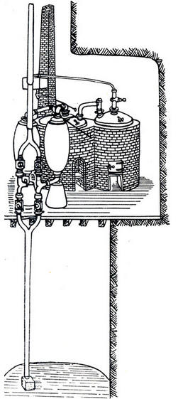
After that, Watt made several more improvements, as a result of which the machine took on the following form. Tubes were connected to both sides of the cylinder: through the lower one, steam entered from the steam boiler, and through the upper one it was discharged to the condenser. The condenser consisted of two tin tubes standing vertically and connected to each other at the top by a short horizontal tube with a hole blocked by a tap. The bottom of these tubes was connected to a third vertical tube which served as an air outlet pump. The tubes that made up the refrigerator and the air pump were placed in a small cylinder of cold water. The steam tube was connected to a boiler, from which steam was released into a cylinder. When the steam filled the cylinder, the steam valve was closed and the piston of the condenser air pump was raised, as a result of which a highly discharged space was obtained in the condenser tubes. The steam rushed into the tubes and condensed there, and the piston rose up, dragging the load with it (this is how the useful work of the piston was measured). Then the outlet cock was closed. In 1768, on the basis of this model, Watt's large machine was built at the mine of the miner Rebuk, for the invention of which he received his first patent in 1769. The most fundamental and important in his invention was the separation of the steam cylinder and the condenser, due to which energy was not expended on the constant heating of the cylinder. The car has become more economical. Its efficiency has increased. For the next few years, Watt worked hard to improve his engine. At the same time, he had to overcome many difficulties, both financial and technical. He entered into a company with the owner of a metalworking plant, Bolton, who provided him with money. There were other problems: the engine required tightness and precise fitting of parts to each other. The piston and cylinder had to be perfectly sized to prevent steam from escaping. Such accuracy was new for the mechanical engineering of those times; there were not even the necessary precision machines. The undercutting of large diameter cylinders seemed to be an almost insoluble problem. As a result, Watt's first machines worked unsatisfactorily: steam escaped from the cylinder, condensers did not work well, steam whistled through the hole in which the piston rod moved, leaked between the walls of the piston and cylinder. I had to create special machines for boring cylinders. (In general, the creation of a steam engine marked the beginning of a real revolution in machine tool building - in order to master the production of steam engines, mechanical engineering had to rise to a qualitatively higher level.) Finally, all difficulties were overcome, and from 1776 factory production of steam engines began. Several fundamental improvements were made to the 1776 machine compared to the 1765 design. The piston was placed inside the cylinder, surrounded by a steam jacket (jacket). As a result, heat loss was reduced to a minimum. The casing was closed from above, while the cylinder was open. Steam entered the cylinder from the boiler through a side pipe. The cylinder was connected to the condenser by a pipe equipped with a steam outlet valve. Slightly above this valve and closer to the cylinder, a second balancing valve was placed. When both valves were open, the steam released from the boiler filled all the space above and below the piston, forcing air through a pipe into the condenser. When the valves were closed, the whole system continued to remain in equilibrium. Then the lower outlet valve was opened, separating the space under the piston from the condenser. The steam from this space was sent to the condenser, cooled here and condensed. In this case, a rarefied space was created under the piston, and the pressure dropped. From above, the steam coming from the boiler continued to exert pressure. Under its action, the piston descended and performed useful work, which was transferred to the pump rod with the help of a balancer. After the piston dropped to its lowest position, the upper balancing valve opened. Steam again filled the space above and below the piston. The pressure in the cylinder was balanced. Under the action of a counterweight located at the end of the balance bar, the piston freely rose up (without doing any useful work). Then the whole process continued in the same sequence. Although this Watt machine, like Newcomen's engine, remained one-way, it already had an important difference - if Newcomen's work was done by atmospheric pressure, then steam did it for Watt. By increasing the steam pressure, it was possible to increase the power of the engine and thus influence its operation. However, this did not eliminate the main drawback of this type of machine - they made only one working movement, they worked in jerks and therefore could only be used as pumps. In the years 1775-1785, 66 of these steam engines were built. In order for a steam engine to be able to power other machines, it was necessary that it create a uniform circular motion. The fundamental difference between such a machine was that the piston had to make two working movements - both forward and backward. Such a double-acting engine was developed by Watt in 1782. The steam here was released first from one side, then from the other side of the piston, and the space on the side opposite the steam inlet was connected each time to the condenser. This problem was solved with the help of an ingenious system of outlet pipes, closed and opened with the help of a spool.
The spool was a valve that moved in front of two holes to pass steam. With each stroke of the valve to one side or the other, one hole opened and another closed, as a result of which the path along which the steam could pass changed. The movement of the spool had a complex character at each extreme position, when one hole was open and the other was closed, it had to stop for a while in order to skip a portion of the steam, and pass the middle position as quickly as possible. The movement of the spool was controlled by a special mechanism located on the shaft. The main part in it was an eccentric.
The eccentric, invented by Watt, consisted of a plate of a special shape, sitting on an axis located not in the center of this plate, but at some distance from it. With this mounting, there was more of the plate on one side of the axle than on the other. The plate itself was surrounded by a ring, to which a rod was attached to move the spool. During the rotation of the plate, its roundness constantly pressed on a new point inside the surface of the ring and, with its wider side, set it in motion. Together with each turn of the shaft, one stroke of the spool occurred. The nature of the rotation of the ring (and, accordingly, the movement of the thrust) depended on the shape of the plate inserted into the eccentric. Through calculations, such a form was selected, which during one revolution caused either acceleration, or deceleration, or stopping of the spool. With the introduction of this device, Watt made the operation of his machine fully automatic. At first, the operation of the engine was observed by a worker, whose duty it was to regulate the supply of steam. If the engine started to give too high speed, it blocked the steam distribution pipe with a special damper and thereby reduced the steam pressure. Then this function was assigned to a special centrifugal regulator, arranged as follows. The movement of the working shaft was transmitted to the regulator pulley. When the latter began to rotate too fast (and therefore the engine speed increased excessively), the regulator balls rose up under the action of centrifugal force and set in motion a valve sleeve and a lever that limited the amount of steam. With a decrease in the number of revolutions, the balls fell and the valve opened slightly.
Given the operation of all these devices, it is easy to imagine the general principle of the machine. From the steam boiler, steam passed through the pipe into space b, and from there, due to the movement of the spool, it was directed to the cylinder either above piston B or below it. When steam entered the space above the piston, the latter descended, and once under the piston, it raised it. There was a valve in the steam pipe that allowed more or less steam to pass, depending on the need. The position of the valve was regulated by a steam centrifugal regulator f. An eccentric e sat on the main shaft, the rod of which SS passed on the other side of the machine under the spool box and, with the help of a lever, either raised or lowered the spool. The movement of the piston B was transmitted to the rod O, which passed completely tightly into the cylinder head, and from it to the movable rocker. At the opposite end of the rocker was part G, which captured the crank of the main shaft K from below. Thus, with each ascent and descent of the piston, there was one revolution of this shaft and the flywheel L sitting on it. The force was transmitted from the main shaft using belts or other means there, where it was supposed to be used. The condenser was located at the bottom of the machine. It consisted of a tank filled with water, which was constantly renewed by means of a pump q, and a tank D where condensation took place. Cold water not only surrounded the tank, but also splashed into it through many small holes. The drained hot water was constantly pumped out with the help of the water pump C. The warm water entered the box and was again pumped out into the steam boiler with the help of the pump Mm.
The creation of a mechanism for transmitting movement from the piston to the shaft required enormous efforts from Watt. Many of the tasks he solved were generally on the border of the technical possibilities of that time. One of the problems was to create the necessary tightness. In a double-acting cylinder, unlike a single-acting cylinder, both sides had to be tightly closed. But since the piston had to have a connection with external parts, a round hole was left in the cover, in which the piston rod (rod) went completely tightly. Watt came up with the idea of putting a tightly screwed thick layer of oiled tow into the lid, along which the rod glided without touching the metal of the cylinder. Moreover, the rod, due to its smoothness, rubbed very little. Another problem was in the movement conversion mechanism itself: after all, in order to transfer the useful work done by the piston when it moved up, it was necessary that the piston rod was rigidly connected to the balance bar. On all previous steam engines, they were connected by a chain. Now I had to think about how to rigidly connect the rod moving in a straight line and the end of the balancer moving along an arc. Watt achieved this by creating a special transmitting device, which is called Watt's parallelogram.
The end of the rocker arm A was articulated here by a linkage ADB with point B of the lever BC connected at point C to some fixed part of the engine. Thus, the whole system had two fixed points of rotation: the center of the balance bar, around which the balance bar oscillated, and point C, around which the lever CB rotated. Point A at the end of the balance bar and point B at the end of the lever CB moved along arcs described from the center of the balance bar and from point C. At the same time, point D on the rod ADB connecting points A and B made movements very close to vertical and rectilinear. This point was connected to the piston rod. Subsequently, Watt improved this transmitting device by obtaining two points connecting rectilinear motion. He connected one of them to the piston rod, and the other to the rod of the auxiliary pump serving the engine. The creation of this transmission device required so much effort from Watt that he considered it his greatest invention. He wrote: "Although I do not particularly care about my fame, I am more proud of the invention of the parallelogram than any of my other inventions."
Then the oscillatory movements of the balance bar were converted with the help of a crank into rotational (since the crank mechanism was patented by Picard, in Watt's first machines, the oscillatory movement of the balance bar was converted into rotational movement using the solar-planetary mechanism created by Watt, as soon as Picard's patent expired, they began to use a crank transmission). Thanks to the rotational movement of the working shaft obtained as a result of all these transformations, the new Watt engine was suitable for driving other working machines. This allowed him to play a revolutionary role in the development of a large machine industry. During the years 1785-1795, 144 such steam engines were produced, and by 1800, 321 Watt steam engines were already operating in England. They were used literally in all spheres of production. Watt's great work was duly appreciated by his contemporaries and descendants. After the inventor's death in 1819, the English Parliament honored his memory with the construction of a marble monument in Westminster Abbey. Author: Ryzhov K.V.
▪ Lever, block, inclined plane
Artificial leather for touch emulation
15.04.2024 Petgugu Global cat litter
15.04.2024 The attractiveness of caring men
14.04.2024
▪ Nanobots to be launched into human veins ▪ Magnetic resonance imaging of a single atom ▪ Computer mouse will prevent stress ▪ A dog has a positive effect on the health of its owner ▪ Combat laser of the third generation
▪ site section Low frequency amplifiers. Article selection ▪ White Crow article. Popular expression ▪ article Protective shutdown relay. Encyclopedia of radio electronics and electrical engineering
Home page | Library | Articles | Website map | Site Reviews
www.diagram.com.ua |


 See other articles Section