|
|


 Arabic
 Bengali
 Chinese
 English
 French
 German
 Hebrew
 Hindi
Hindi Italian
 Japanese
 Korean
 Malay
Malay Polish
 Portuguese
 Spanish
 Turkish
 Ukrainian
 Vietnamese
|
ENCYCLOPEDIA OF RADIO ELECTRONICS AND ELECTRICAL ENGINEERING Elimination of interference from computer TV tuners in cable television networks. Encyclopedia of radio electronics and electrical engineering
Encyclopedia of radio electronics and electrical engineering / Television, video equipment The author of the published article shares his experience in combating interference created by television tuners on personal computers. In connection with the intensive development of digital technology and its implementation in areas where analog technology has so far dominated, ordinary users are sometimes faced with the acute question of the compatibility of various technologies at the household level. A striking example is the use of TV tuners (hereinafter referred to as tuners) for receiving analog television, existing in the form of expansion cards for personal computers (PCs). Along with high-quality and relatively expensive models, which are not even tuners as such, but full-fledged video capture cards, there are a large number of simple models of frankly low quality, captivating with their cheapness. The second type of device includes, for example, cheap clones based on the SAA713 processor. An inexperienced user does not even imagine that by buying such a card, he is acquiring a “package” of problems not only for himself, but also for his unsuspecting neighbors. Problems are identified in public networks, such as cable television, immediately after installing the tuner. The fact is that the tuner contains both an analog (the television receiver itself) and a digital part, and “docking” them in one product while maintaining signal quality is a very difficult matter, complicated by the well-known fact that through the lines of the PC itself it can HF current of several, or even tens of amperes, can flow. If the filtering quality is low, you can observe the result in the form of strong noise in the image. Naturally, the tuner not only creates interference to itself, but also generously distributes it to the outside world. If the purchased tuner is designed to receive a signal from the air, the matter, of course, is very unpleasant, but it will remain your personal one. But if such a tuner is connected to a cable network, rest assured that your neighbors will also fully “enjoy” the “high-quality” image, and you yourself, if you also have a regular TV in your apartment connected to the same network. On the other hand, if characteristic strong interference in the form of a dozen vertical light lines is observed on the TV screen, then with a high probability we can say that a “computer” tuner is turned on somewhere nearby. The problem arose simultaneously with the advent of tuners, but a clear solution, other than a “banal” replacement of the model used, has not been found to this day. Meanwhile, the issue of price is really important, and often decisive - after all, not everyone will buy a TV for themselves when it is possible to purchase a tuner for 10...30 dollars, even if the image quality is not the best. By the way, interference on a monitor screen is subjectively less noticeable than on a TV screen. The type and level of interference usually does not depend on the software used, driver version or operating system, but is a purely hardware feature of the device. This article summarizes data obtained from publicly available but few sources on the Internet [1,2], which provide adequate results, and is supplemented by our own experience. The conference [1] determined (and it is logical to assume) that interference based on its source of origin can be clearly divided into two groups: interference in power supply circuits and in information transmission circuits (PCI bus). Moreover, it was noted that in the first stages of the development of computer technology, interference from power supplies (PSUs) predominated; today, most likely, one will have to deal with interference from data transmission circuits. It is quite difficult to distinguish them visually, so it is necessary to follow active diagnostic methods according to the principle: do it - see what happened. There are also several methods for eliminating interference, but in reality we can talk about three. The first way is to move the channel selector 1,5...2 m behind the PC case. The method does not give predictable results and is clearly unprofitable, since it is associated with the dismantling of the selector and the presence of a “bundle” of shielded wires from the tuner board to the selector according to the number of pins of the latter. This method probably only saves you from interference caused directly to the selector block inside the PC case. In any case, you shouldn't start with this. The second way is to supply power to the selector from a separate stabilized power source. This method is simple and effective if interference is generated by switching power supply circuits. Before starting to implement this method, it is advisable to evaluate the expected effect. To do this, determine the location of the oxide capacitor of the selector power filter on the tuner board. Typically this is a capacitor with a capacity of 100-220 uF, located near the short end of the selector housing, from the positive terminal of which the printed conductor goes to the three rightmost combined pads of the top row of the PCI connector (+5 V power line). This, as a rule, is the only sufficiently wide conductor, from which there are also branches for powering the microcircuits and several more oxide capacitors of approximately the same capacity are connected. In parallel with the filter capacitor found on the board, an additional capacitor with a capacity of 1000-2200 μF for a rated voltage of 16 V is soldered, observing the polarity, and always a ceramic capacitor with a capacity of 0,1-0,47 μF. If the specified procedure did not produce any visually noticeable effect, the full implementation of the method will most likely also not lead to the desired result. However, it is recommended to leave the hanging capacitors on the board. If some positive effect appears, then the selector power supply terminal, connected to the positive terminal of the found filter capacitor, is disconnected from the outside, and connected to the +5 V ±5% output of an additional external power supply, which I recommend assembling according to a conventional transformer circuit with a 7805 integrated stabilizer in a typical connection . No heat sink is required for the stabilizer. Output-5 V (common) of the power supply is connected to the common wire of the tuner board as close as possible to the selector body, preferably to one of its “legs”. A ceramic capacitor with a capacity of 0,1-0,47 μF must be installed between the selector power output and the common wire. However, the described methods in some cases do not lead to complete elimination of the defect, and sometimes do not give any result at all, except for some change in the interference pattern.
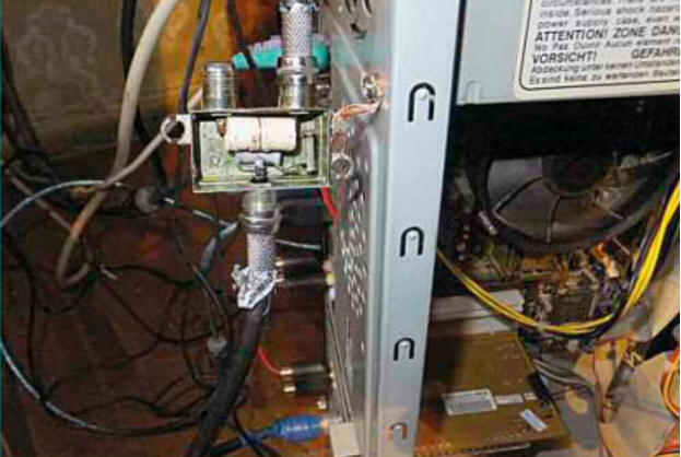
Then you should use the third method, popularly known as the “poke method.” This is the method that gives the best results. Its essence is to experimentally determine the point on the selector body or tuner board, the galvanic connection of which with a point on the PC case leads to the best effect. The position of the point on the PC case is also determined experimentally. The physical meaning of this is quite clear. The housing of the antenna connector (RF input of the selector) does not have a direct galvanic connection with the PC housing. The metal card mounting strip around the antenna connector and V/FM connector usually has holes 1.2 mm larger in diameter. Thus, the sensitive input of the tuner and the selector elements are connected to a common wire (PC case) through rather long printed conductors of small cross-section, passing along the tuner board and further along the entire motherboard, as well as through connectors and power supply wires, which are not intended for transmission at all HF voltage. The current flowing through the power and data wires is the cause of powerful interference. Creating a direct galvanic connection between the selector body (connector) and the PC body allows you to almost completely get rid of them. On the tuner side, the optimal connection points have been determined: this is the antenna connector housing, the V/FM connector housing, or a point on the selector housing (selected experimentally). To one of them you should solder a copper wire with a cross-section of 4 mm2 (necessarily multi-core) or the braid of a piece of coaxial cable. The wire is tinned from one end to 2.3 mm. The connection point to the PC case is usually selected according to the shortest distance from the selected point on the board. The wire should not be connected to the mounting bar, since the point may not be optimal, and the bar often does not have a reliable screw connection to the housing. The location is determined more accurately by pressing the wire tightly against the body and moving it along the surface. I recommend pre-cleaning the metal surface with fine sandpaper. In a place that corresponds to maximum noise suppression, a hole is drilled and the wire is secured using a reliable threaded connection. Some users simply “drive” a suitable screw between the connector body and the card mounting plate. But this does not always achieve the desired effect for the reason mentioned above. Supporters of the experiments should also be warned that direct connection of any of the tuner points to the common wire inside the power supply, even using a coaxial cable, does not affect the manifestation of this type of interference. But in some very “severe” cases, the method described above does not allow you to completely get rid of interference. But the method proposed below suppresses interference even in such cases. It is a more “beautiful” radio engineering version of the third method and consists of the following. The antenna cable is cut at a distance of 20.30 cm from the tuner input and equipped with standard connectors with a threaded connection for connection to a passive signal splitter. In the housing of the splitter in two directions, a high-pass filter is assembled according to the diagram shown in Fig. 1. The inductor coil contains 3,5 turns of PEV-2 0,15 wire, wound turn to turn on a paper frame with a diameter of 8 mm. Capacitors are ceramic (for example, KT-1, KTK or K10), with a capacity of 33-56 pF. The filter is connected to the feeder gap. The housing has an external contact with an M3 threaded connection. With its help, the filter is connected to one of the PC power supply mounting screws with a piece of stranded copper wire with a cross-section of 4 mm2 and a length of 3.4 cm (the wire is clamped under the head of the mounting screw, preferably using an additional ribbed washer). The resulting connection ensures reliable galvanic contact of the antenna cable braid with the PC case and at the same time mechanical fastening of the filter (Fig. 2). The photo also shows the tuner board with additional power filter capacitors.
The high-pass filter provides additional attenuation of interference penetrating from the tuner into the cable network. To prevent the antenna connector from contacting the case in an unintended place, the fastening bar is temporarily separated from the tuner board, the outer side of the connector is wrapped with one or two layers of adhesive tape and the bar is returned to its place. If there are other television receivers in the apartment, and there is only one cable input, then it is better to connect through passive or active splitters in the required number of directions. A passive splitter should not consist of wires alone, as is often the case, but should correspond to the classic circuit shown in Fig. 3. The resistance of each resistor is calculated using the formula R = R0 (N-1)/(N+1), where R0 = 75 Ohm - characteristic impedance; N is the number of directions. For example, for a two-way splitter the standard resistance value is R = 24 ohms.
The insertion attenuation coefficient for a two-channel splitter is -6 dB and more than -9 dB for a three-channel splitter, so it is not advisable to use resistive splitters for a larger number of directions. It is advisable to place the splitter at the same distance from the TV receivers or closer to a regular TV. If the signal level allows, instead of a splitter it is advisable to use a simple -20 dB attenuator according to the diagram in Fig. 4. This will also significantly reduce the level of interference from the PC tuner. It is advisable to use resistors C2-10, but ordinary MLT-0,125 are also acceptable. It should be noted that the degree of manifestation of any interference is significantly reduced with a strong useful signal, so special attention should be paid to the general serviceability of the cable system and compliance with the rules for installing HF signal circuits. You can also use an additional television signal amplifier, for example [3].
Literature
Author: D. Pankratiev
Alcohol content of warm beer
07.05.2024 Major risk factor for gambling addiction
07.05.2024 Traffic noise delays the growth of chicks
06.05.2024
▪ New line of noise protection filters TDK-Lambda
▪ section of the site Car. Article selection ▪ article The era of stagnation. Popular expression ▪ article Who started wearing leggings? Detailed answer ▪ Article Black pepper. Legends, cultivation, methods of application ▪ article Grounding system TN-CS. Encyclopedia of radio electronics and electrical engineering ▪ article Wireless home bell. Encyclopedia of radio electronics and electrical engineering
Home page | Library | Articles | Website map | Site Reviews
www.diagram.com.ua |


 Leave your comment on this article: