|
|


 Arabic
 Bengali
 Chinese
 English
 French
 German
 Hebrew
 Hindi
Hindi Italian
 Japanese
 Korean
 Malay
Malay Polish
 Portuguese
 Spanish
 Turkish
 Ukrainian
 Vietnamese
|
ENCYCLOPEDIA OF RADIO ELECTRONICS AND ELECTRICAL ENGINEERING BVG: Characteristics, features of operation and repair. Encyclopedia of radio electronics and electrical engineering
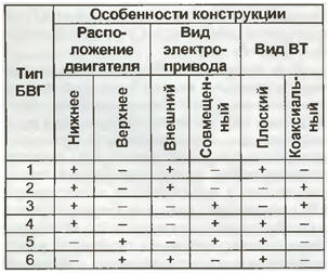
Encyclopedia of radio electronics and electrical engineering / Телевидение VVG (video head unit or rotary head unit) can be considered the main unit of any VCR and camcorder. The author of the published article talks about its design, classifies possible options for execution, describes the disassembly / assembly process. All this, we hope, will help repairmen with great knowledge of the matter to approach the repair of such equipment. Attempts to record a television signal on magnetic tape were made as early as the forties of the last century. For these purposes, at first they wanted to use ordinary tape recorders with stationary magnetic heads, but with an increased feed speed and a larger width of the magnetic tape. Many attempts were successful, but the capabilities of devices with a longitudinal recording method completely ruled out their widespread use due to the short recording time. For example, in 1953, RCA (USA) demonstrated an installation with a tape speed of 9 m/s. The duration of the recording on a roll with a diameter of 43 cm and a tape width of 12,7 mm was only about four minutes. All subsequent successes in recording television and other broadband signals are associated with the use of magnetic heads rotating at high speed. For the first time, this method was implemented in 1956 in a video recorder from AMPEX (USA) with a cross-line recording method. The tape pulling speed in it was reduced to 39,7 cm/s [1]. Domestic developments are not far behind. In 1959, the first video recorder, developed at the Lenkinap plant, was shown in Leningrad. It should be noted that at that time video recording equipment in the United States was classified as a strategic product and could not be sold to the CMEA countries, so our first video recorder was made entirely on domestic elements and on the basis of our own developments. Further advances in video recording are due to the use of a slanted-line method of recording video signals on a tape moving at a relatively low speed. Initially, it was used in reel-to-reel, and then in cassette devices. Despite numerous versions, the main unit ("heart") of any VCR has been and remains a block of rotating heads (RHG). It is used to record not only television, but also audio signals, as well as various information in analog and digital form. In the early 70s, the Pulse Code Modulation (PCM) method was used for professional sound recording. It was practically tested in a system consisting of a U-MATIC video cassette recorder and a SONY PCM-1630 converter. No modification of the serial video recorder was required, since two-channel stereo audio signals were converted by the PCM-1630 prefix to PCM signals, and then to a pseudo-television signal. With the advent of household video cassette recorders, this method of sound recording has also found application for domestic purposes. PCM set-top boxes were widely distributed in the Japanese domestic market in the early 80s. Recording sound in this way is also currently used in HI-8 format equipment (mainly in video cameras). Rotating heads for recording only audio signals are also used in digital tape recorders of the R-DAT format (DIGITAL AUDIO TAPE), the sale of which began in 1987. The format was initially considered as a household one, but such tape recorders were not widely used in everyday life due to the high price. Nevertheless, many firms continue to produce R-DAT tape recorders even now. They are now designed mainly for professional use and for lovers of high-quality sound reproduction (FOSTEX, HHB, SONY, TASCAM, etc.). Naturally, BVGs are used both in household video cassette recorders and in the video recorder sections of camcorders (video cameras) of the VHS, VHS-C, VIDEO-8, S-VHS, S-VHS-C, MINI-DV formats. It should be noted that the signalograms of the VHS, VHS-C, S-VHS and S-VHS-C formats are the same, that is, the "compact" versions do not represent separate formats in the full sense. However, BVGs in VHS-C/S-VHS-C equipment are fundamentally different from their full-size prototypes, so we will consider them here as different formats. RVR serves as the "heart" of VCRs insofar as the quality of recorded and reproduced video, and often audio signals, directly depends on their characteristics. Failures and malfunctions of various components and parts of the BVG are a frequent phenomenon. Therefore, a detailed presentation of the features of their design and functioning is necessary for the effective repair and adjustment of home video recorders and camcorders. The design features, geometric dimensions and characteristics of the BVG are primarily determined by the recording format. If we count from the time of the appearance of the first video recorders to the present day, then we can call many different formats of magnetic recording as rotating heads. Some of them were extremely widespread, while others, on the contrary, remained only on paper. One of the definitions of the concept is as follows: a recording format is an ordered arrangement of lines and tracks on the surface of a tape, magnetized under the action of various signals, ensuring the implementation of the principle of interchangeability and unambiguously indicating the method of recording and reproducing information [2]. The most significant formats are usually registered with the IEC - International Electrotechnical Commission (IEC). In the 90s, digital formats appeared. The well-known firms SONY (DIGITAL VETASAM, BETACAM-SX, DVCAM), MATSUSHITA (PANASONIC-D3, D5, DV, DVCPRO), JVC (DIGITAL-S) are fighting for their wide introduction. This is a professional format. As for domestic devices, the situation has been determined, and most manufacturers produce equipment in the MINI-DV format (mainly video cameras). Unfortunately, in our country, household digital video cameras, and even more so video recorders, have not yet received noticeable distribution due to the high price ($1000 or more). In addition, to fully utilize their capabilities, you need a good computer with a capture board. MINI-DV cassettes are three times more expensive than HI-8 cassettes, which naturally makes distribution of such equipment even more difficult. With this in mind, let's consider only the BVG used in the widespread consumer video equipment of the VHS/VHS-C/S-VHS/S-VHS-С, VIDEO-8, HI-8 formats. The fulfillment of the requirements set by the format can be achieved in various ways, so the designs of the BVG are very diverse. Since when carrying out repairs, in particular, when replacing video heads, a clear understanding of the design of a particular BVG, the procedure for its disassembly/assembly and maintenance features is required, it is advisable to classify the designs of various manufacturers. Regardless of the company, BVG contain the following nodes: the upper cylinder (VC), on which magnetic heads are installed; rotating transformer (VT); the lower cylinder (NC), obliquely placed on the frame of the LPM; non-contact DC motor (BCPT) of BVG electric drive. In some models of TOSHIBA video recorders, the BVG also includes a preamplifier with an electric generator feeding it (TOSHIBA - V856G, etc.). JVC has included in the BVG of a number of video recorders units that provide the required inclination relative to the chassis at various tape speeds to obtain noise-free viewing (JVC - HR-DD949EE, etc.). Despite the fact that one of the format conditions is considered to be the diameter of the BVG (for VHS - IEC publication 774 in 1983), it is possible to obtain a signalogram corresponding to a particular format at its various diameters. In particular, in VHS equipment, RVRs with a diameter of 62 (the main part of the equipment) and 41,33 mm (in full-size video cameras) are used. Small-sized BVGs are widely used in most models of VHS-C / S-VHS-C camcorders. The LPM of such camcorders cannot be used to work with conventional VHS cassettes. At the same time, using a special adapter, a compact cassette can be installed in any VHS VCR. Therefore, format compatibility is incomplete. This is also why the VHS-C format is often referred to as an independent one. Most 40mm instruments use a 26,7mm diameter RGU. In video cameras, a BVG with a diameter of 505 mm is also used (SONY - CCD-TR180E, etc.). The angle of its wrapping with the tape depends on the diameter of the BVG: in VHS / S-VHS - 270 °, VHS-C - 8 °, VIDEO-8 / HI-220 - 26,7 ° (with a diameter of 360 mm - almost XNUMX °). From the whole variety of BVG designs, one can distinguish (according to the author) seven conditional options (types) with different technical solutions, six of which are described in the table. The seventh type includes special RGU designs with rotating preamplifiers, with the so-called movable video heads, variable tilt angle, etc.
On fig. Figure 1 shows the first three types of BVGs, of which type 1 is used in the VIDEO-8 format with a BVG diameter of 40 mm, and types 2 and 3 are used in VHS/S-VHS formats with a BVG diameter of 41,33 and 62 mm, respectively.
On fig. Figure 2 shows the NCs of these types of BVG from below, of which type 1 is used in SAMSUNG video cameras - VP-U12 / U15, etc., type 2 - in PANASONIC video cameras - NV-V9000 / MS4 / AG455 / AG-DP200, and type 3 - in PANASONIC VCRs - NV-ND70/90/95/100/F55/65/FS88/200/ AG5260/5700 and others by MATSUSHITA.
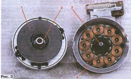
Each company classifies specific names of BVG in its own way. They are usually not marked, since this is a prefabricated unit. Even the VC marking is far from always available, and even more so - NC and VT. However, having information about the applicability of BVG units, in many cases it is possible to select analogues for devices that are difficult to repair (the so-called abandoned ones). It makes little sense to search for such information in the literature, since manufacturers are reluctant to provide such information for general access. Therefore, it is very useful for repairmen and practicing radio amateurs to record the markings of the units of the equipment being repaired in their own archive. For example, let's consider the applicability of some NCs from MATSUSHITA (the applicability of CCs requires separate consideration). The NC marking is usually painted on its side surface. NTs VEG1343A is used in the line of two-head video players and VCRs PANASONIC 1997-1999. production: NV-SP10/SR30/50/55/60/PO5 and others. VCRs PANASONIC series SUPER DRIVE: NV-SD0758/80, etc. In stereo video players PANASONIC - NV-SR90/20/30/HP1023 with four heads used NC VEG20. PANASONIC - NV-F25/F70 stereo VCRs with six heads use VEG80 NC. Under certain conditions, it is interchangeable with the NTS VEG90 installed in PANASONIC VCR models - SUPER DRIVE: NV-ND10/1220/55/65/AG0766, etc. VCs, and even more so the BVGs themselves, are very expensive, and often so scarce that in some cases, if they break down, VCRs, and especially camcorders, become completely unrepairable or the repair cost is unrealistic for the owners. Therefore, when carrying out work on the disassembly / assembly of the BVG, special care should be taken. In many models of PANASONIC VCRs with type 3 VCRs, problems often occur due to the drying of the lubricant, contamination and wear of the plain bearings. In this case, a mechanical rumble appears, the image seems to sway horizontally, stereo sound channels are turned off, etc. As a rule, such defects can be eliminated, which requires disassembly / assembly of the BVG. Before starting it, it is necessary to fix the VC with a gasket, inserting it into the gap between the VC and NC. For this purpose, for example, a safety razor blade in a package is suitable. Dismantling begins with unscrewing the three fastening screws 1 shown in fig. 1, and the current collector of the common wire must be previously removed. The slots of these screws generally require a special screwdriver, but a 1,6 or 1,5 mm hex socket wrench can be used. Sets of such keys are available on radio markets (for example, a set of VIDEO SERVICE TOOL VHS/BETA 8034-549-11, etc.). Then cover 2 is removed, which simultaneously serves as the upper thrust bearing. It should be borne in mind that the magnet 1 of the rotor of the engine shown in fig. 3 in the disconnected state, tightly attracted to the stator 4, therefore, in no case should the VC be rotated (the previously inserted gasket protects the video heads from damage).
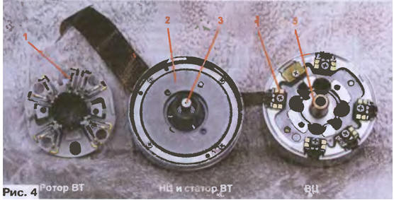
The next operation is to remove the split fixing washer located under cover 2 (see Fig. 1). To remove it, in the general case, you need a special tool, but miniature pliers or tweezers can also be used. The width of their tips should be no more than 1,6 mm. The frequently practiced picking out of washers with screwdrivers is not recommended, since this usually leads to damage to the engine rotor hub made of aluminum alloy, after which the normal operation of devices, especially stereo and mounting ones, can be achieved very rarely due to misalignment of the CC and NC and the appearance of eccentricity . The next stage is the removal of the CC with the rotors of the engine and VT. This must be done very carefully, without violating alignment, so as not to damage the fragile ferrite magnetic cores of the VT and its windings. Then the steel bearing shaft 3 (Fig. 3) and the inner surface of the sleeve of the plain bearings 2 are cleaned of dirt with an alcohol-gasoline mixture (or alcohol, or gasoline) and the bearings are lubricated with a small amount of sewing machine oil (preferably refined grades or the so-called hourly ). After that, the VC is set to its original position, not forgetting to insert the fixing gasket. It is not necessary to replace the split washer, since the rotor magnet is attracted to the base with quite sufficient force. And finally, they close the shaft with cover 2 (see Fig. 1), having previously cleaned and lubricated its inner surface with a special non-thickening grease (morliton, refined petroleum jelly, etc., grease for cars cannot be used). The fixing screws 1 are screwed in and tightened gradually and alternately in order to prevent the cover from tilting. In most cases, the operations performed are quite enough to restore the normal silent operation of the BVG. In rare cases, it may be necessary to polish the inner surface of bearings 2 (fig. 3) with a cotton cloth rubbed with polishing paste. A BVG of type 2 has a similar design. It is shown in disassembled form in fig. 4. Disassemble it after unscrewing the screws 3 and removing the cover 4 (see Fig. 1). Differences from BVG type 1 lie in the absence of a split fixing washer and in the connection of the outputs of the video heads VC 4 (Fig. 4) with the windings of the rotor VT 1 through gold-plated spring contacts (in BVG type 1 - soldered connections). On fig. 4, the motor rotor 2, the bearing shaft 3 and the bearing sleeve 5 are also visible.
Design features and methods for disassembling/assembling BVG type 5 are considered in [3], and other types - in the albums "LPM of VCRs and camcorders, repair, adjustment", sold on radio markets. The largest number of BVG failures, including due to natural wear, falls on the CC. Their designs and types, there are many dozens. Information on their application and interchangeability is of great practical interest for both repairmen and radio amateurs. This will be discussed in other publications. Literature
Author: Yu.Petropavlovsky, Taganrog
Energy from space for Starship
08.05.2024 New method for creating powerful batteries
08.05.2024 Alcohol content of warm beer
07.05.2024
▪ A new record for quantum teleportation ▪ door at the bottom of the lake ▪ Seoul Semiconductor SunLike LED is the safest ▪ XTR305 - industrial analog signal driver with diagnostics
▪ section of the site Biographies of great scientists. Article selection ▪ article He whipped himself, the non-commissioned officer's widow whipped herself. Popular expression ▪ article Whose clothes had more than 10 buttons sewn on? Detailed answer ▪ Article Pediculosis. Health care ▪ article Indicator of metal objects. Encyclopedia of radio electronics and electrical engineering ▪ article Charger 5...10000 mAh. Encyclopedia of radio electronics and electrical engineering
Home page | Library | Articles | Website map | Site Reviews
www.diagram.com.ua |


 Leave your comment on this article: