|
|


 Arabic
 Bengali
 Chinese
 English
 French
 German
 Hebrew
 Hindi
Hindi Italian
 Japanese
 Korean
 Malay
Malay Polish
 Portuguese
 Spanish
 Turkish
 Ukrainian
 Vietnamese
|
ENCYCLOPEDIA OF RADIO ELECTRONICS AND ELECTRICAL ENGINEERING Quasi-parallel channel - a block of pure sound. Encyclopedia of radio electronics and electrical engineering
Encyclopedia of radio electronics and electrical engineering / Телевидение The sound quality of television programs on many domestic and foreign televisions, unfortunately, remains quite low, especially if the programs are accompanied by captions. Quasi-parallel channel is a radical way to provide "clean" high-quality sound. There is also the problem of receiving sound on TVs that only receive broadcasts in the B/G standard. This will be discussed in the published article. Foreign video equipment (TVs, VCRs, etc.) continues to arrive in Russia and other CIS countries in various ways. which is designed to receive television signals exclusively from the PAL system. In our country, such devices practically do not create problems with obtaining images, since almost all foreign televisions have decoders that convert video signals of the SECAM television system adopted in our country into video signals of the PAL (or other) system [1.2]. You just have to keep in mind that in Western European countries the image IF is 38.9. and not 38 MHz, as in our standard [3]. This may lead to the need to adjust the output filter of the channel selector, although such cases are quite rare. The situation is much more complicated in foreign TVs with sound, which do not have a multi-system sound unit. After all, it is known that at present, depending on the separation of image and sound carriers in various radio frequency standards, the second IF of sound can be equal to 4.5; 5.5; 6 and 6.5 MHz Usually such TVs operate on one of them 14]. Thus, for standards B, G, H it is equal to 5,5 MHz. Therefore, for sound when receiving a television signal of D/K standards, in which the second IF is 6.5 MHz, it is necessary to convert this frequency to a second IF of 5.5 MHz. However, conversion alone cannot provide good sound, since the first IF sound (31,5 MHz of our standard and 32,5 MHz of standards B, G. H) is located on the extended shelf of the frequency response of the UPCH. which ensures the passage of both IFs. Problems also arise in all devices that provide for joint processing of video and audio signals on the first IF. And there are quite a lot of such televisions, both foreign and domestic. In them, the second IF signal is isolated when detecting a full color television video signal (PCTV) as a result of the beats of the first IFs. This inevitably leads to mutual influence of brightness. color and sound components and, consequently, to the appearance of significant distortions. The signal of the second IF arrives at the input of the UPChZ distorted, which complicates the operation of its limiter. As a result, the selected 3H signal contains noise, which is especially noticeable when transferring titles on the image. It is impossible to eliminate them and obtain good sound by replacing the filter in the UPCHZ channel or converting the second IF. To solve this problem in devices designed to receive television signals of standards B, G, H, and to improve the sound in them (this also applies to domestic televisions), radio amateurs resort to various methods. One of them is the use of the so-called quasi-parallel channel. It seems to be the most effective technical solution, since it provides separate detection of video and audio signals, which makes it possible to successfully suppress unwanted video components in the audio channel and reduce the level of interference by approximately 10 dB [5]. Analysis of the construction and practical repetition of quasi-parallel channel blocks, for example, considered in [6]. and converters of the second IF shows that they are difficult to manufacture and configure. Therefore, to eliminate the noted shortcomings, radio amateurs are offered a relatively simple version of a quasi-parallel channel - a “pure” sound block. Its circuit diagram is shown in Fig. 1. and the appearance is shown in Fig. 2.
The main purpose of the block is to amplify and convert the audio signal of standards B. G. N into the signal of the second IF of standards D, K, L, K1 in the first full-level IF mode (after the channel selector), implementation of a two-channel UPCH, which will be discussed below, improvement not only sound quality, but also radio channel parameters. This unit can be used in foreign TVs and VCRs and in domestically produced devices. In televisions, it provides an improvement in the basic technical characteristics of the sound path: a significant increase in sensitivity and noise immunity; complete elimination of noise in the soundtrack of television programs (including with captions); improvement of sound quality in any standards with weak signals in the antenna, and it depends little on their level , since the block provides an AGC of about 60 dB. A disadvantage of the unit is the need to adjust the demodulator circuit of the UPCHZ device in which it is mounted. The unit was designed for use in the LEONARDO-1512 TV from PHILIPS, the channel selector of which has a symmetrical output. However, it can also be connected to a selector with an unbalanced output. In this case, the IF2 signal input (see Fig. 1) must be connected to the common wire. From the output of the channel selector, IF image and audio signals are supplied to the symmetrical input (pins 1 and 16) of the DA1 microcircuit. The selected signal of the second IF sound of 6.5 MHz passes through the piezoceramic SAW bandpass filter Z1 to the TV's UPCHZ. Filter Z1 suppresses the first IF sound of 32.5 MHz. Capacitor C4 filters the AGC voltage. The voltages indicated in the diagram are measured at a current consumed by the unit of 18 mA. The current spread along the power circuit can be in the range from 17 to 27 mA, which is due to tolerances on the elements of the microcircuit. The block is well matched with the output of the channel selector and with the input of the UPCHZ. does not bypass the selector output and has no effect on the image. It also provides the ability to preserve (if necessary) the “native” standard in the device while improving sound quality. The block uses capacitors K10-47. K10-49 and ceramic. Resistors - MLT. Throttle L2 - DPM-0.1. Filter SFE (Z1) can be replaced with filter FP1 P8-62.02. Coil L1 is wound turn to turn on a plastic frame having a carbonyl iron trimmer. The outer diameter of the frame is 3...5 mm, height - no more than 15 mm. The coil contains five turns of PEV-1 0.25 wire. All elements of the block are mounted on a printed circuit board made of single-sided foiled fiberglass, the drawing of which is shown in Fig. 3.
Resistors R1. R2 and inductor L2 are installed perpendicular to the board, and capacitors C3 and C7 are soldered on the side where the printed conductors are located. When installing in a specific model, if the TV in front of the UPCHZ includes a bandpass filter for the required second IF, and in front of it is an input circuit of RC elements, the block can be simplified by eliminating the filter Z1 and resistor R2 (their connection points are connected by jumpers). The output of the block is connected to the input circuit of the filter of the device, having previously broken the conductor going to it. If the device filter is designed for another second inverter. then it needs to be replaced. Inside the device, the block is secured with a metal strip measuring 10x25 mm. which is first soldered to side A of the printed circuit board, and then, together with the block, to the channel selector screen in a convenient place and in any position. For unit connections in the device, MGTF wire is used (shielded wires are not used). The IF1 and IF2 signal inputs are connected to the channel selector outputs without disturbing the existing installation. If the selector has an unbalanced output, then the IF2 signal input is connected to point B on the board (with a common wire). It is recommended to remove the +12 V voltage to the block before the decoupling resistors in the circuits of this power source To tune the block, first set the L1 coil trimmer to the middle position. Then turn on the TV to the first program program and by rotating the trimmer of the standard UPCH demodulator circuit counterclockwise, you get the highest volume and the best quality (without interference and noise) of the sound. Next, the circuit L1C7 of the block is configured in the same way. This adjustment of both circuits is repeated two to three more times. The result of fine tuning should be almost complete suppression of the video signal at the output of the unit and “pure” audio of the received TV program, and finally, check it on all other working channels. If necessary, the adjustment of the contours is refined until a silent sound is obtained. In order to provide two-standard audio in foreign video equipment or replace, if necessary, a failed UPCH chip (for the LEONARDO-1512 TV this is TDA8190. and provided that its other devices are functioning [2]). A fairly simple two-standard UPCHZ was developed. the schematic diagram of which is shown in Fig. 4.
The current consumed by the block is 27 mA. The appearance of such a PPCHZ is shown in Fig. 5.
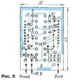
It can be used in devices of both foreign and domestic production. Its disadvantage is the need to use a switch to manually switch from one sound standard to another. The signal of the second IF from the output of the sound block described above is supplied to the input of the UPCHZ. Depending on the value of the second IF (5.5 or 6.5 MHz), switch SB1 turns on the microassembly DA2 (at 5,5 MHz) or DA3 (at 6.5 MHz). It should be borne in mind that when the sound block works together with a two-standard UPCHZ, filter Z1 in the sound block must be replaced with a jumper, since the UPChZ has its own filters 72 and Z3. UPCHZ microassemblies operate according to the following scheme: limitation - detection - amplification. Resistor R3 provides the required output signal level, and capacitor C3 stabilizes the DC voltage at pin 8 of the microassemblies and filters out noise. From the output of the UPCHZ the signal is fed to a 3Ch power amplifier. in which the volume is adjusted. The block uses MLT resistors and any ceramic and oxide capacitors. All parts of the UPCHZ are mounted on a printed circuit board, the drawing of which is shown in Fig. 6.
The block uses a P2K or PKN-61 switch. The switch with the board is attached to a duralumin corner bracket, which is screwed into a selected convenient place on the device. The resistors on the board are installed perpendicular to it. The block is placed in a tin screen 28 mm high. The screen is soldered to the common wire of the unit board on three sides, as well as to pad B. The screen is covered with lids at the top and bottom. The unit is connected to the device via the RG1N-1-1 connector (see Fig. 5). Literature
Author: E. Gaidel, Smolensk
Alcohol content of warm beer
07.05.2024 Major risk factor for gambling addiction
07.05.2024 Traffic noise delays the growth of chicks
06.05.2024
▪ Football field in one gram of the substance ▪ Kingston HyperX DDR4 memory modules ▪ Transmission of radio signals with almost no energy consumption
▪ section of the site Interesting facts. Selection of articles ▪ article In all Ivanovskaya (shouting, yelling, roaring). Popular expression ▪ article Where can I send a letter through an underwater mailbox? Detailed answer
Home page | Library | Articles | Website map | Site Reviews
www.diagram.com.ua |


 Leave your comment on this article: