|
|


 Arabic
 Bengali
 Chinese
 English
 French
 German
 Hebrew
 Hindi
Hindi Italian
 Japanese
 Korean
 Malay
Malay Polish
 Portuguese
 Spanish
 Turkish
 Ukrainian
 Vietnamese
|
ENCYCLOPEDIA OF RADIO ELECTRONICS AND ELECTRICAL ENGINEERING Demonstration ultrasonic installation. Encyclopedia of radio electronics and electrical engineering
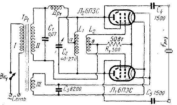
Encyclopedia of radio electronics and electrical engineering / Electronics in everyday life The article describes the design of the simplest ultrasonic setup designed to demonstrate experiments with ultrasound. The setup consists of a generator of ultrasonic vibrations, an emitter, a focusing device, and several auxiliary devices that make it possible to demonstrate various experiments that explain the properties and methods of using ultrasonic vibrations. Using the simplest ultrasonic setup, one can show the propagation of ultrasound in various media, the reflection and refraction of ultrasound at the boundary of two media, and the absorption of ultrasound in various substances. In addition, it is possible to show the production of oil emulsions, the cleaning of contaminated parts, ultrasonic welding, ultrasonic liquid fountain, the biological effect of ultrasonic vibrations. The manufacture of such an installation can be carried out in school workshops by high school students. The installation for demonstrating experiments with ultrasound consists of an electronic generator (Fig. 1), a quartz converter of electrical oscillations into ultrasonic ones, and a lens vessel (Fig. 2) for focusing ultrasound. Only the power transformer Tr1 is included in the power supply, since the anode circuits of the generator lamps are fed directly with alternating current (without a rectifier). Such a simplification does not adversely affect the operation of the device and at the same time significantly simplifies its layout and design. The electronic generator is made according to a push-pull circuit on two 6PZS lamps connected according to a triode circuit (the screen grids of the lamps are connected to the anodes). The circuit L1C2, which determines the frequency of the generated oscillations, is included in the anode circuits of the lamps, and the feedback coil L2 is included in the grid circuits. A small resistance R1 is included in the cathode circuits, which largely determines the mode of the lamps.
The high-frequency signal is fed to the quartz resonator through the coupling capacitors C4 and C5. Quartz is placed in a hermetic quartz holder (Fig. 2) and connected to the generator with wires 1 m long.
In addition to the details considered, there are also capacitors C1 and C3 in the circuit, as well as an inductor Dr1 through which the anode voltage is applied to the anodes of the lamps. This inductor prevents the high frequency signal from being short-circuited through capacitor C1 and the inter-turn capacitance of the power transformer. The main home-made parts of the generator are coils L1 and L2, made in the form of flat spirals. For their manufacture, it is necessary to cut out a wooden template. Two squares are cut out of a board 25 cm wide, which serve as the cheeks of the template. In the center of each cheek, holes should be made for a metal rod with a diameter of 10-15 mm, and in one of the cheeks, a hole or groove 3 mm wide should be cut for attaching the coil output. A thread is cut on a metal rod at both ends and cheeks are placed between two nuts at a distance equal to the diameter of the wound wire. On this, the manufacture of the template can be considered complete and proceed to winding the coils. The metal rod is clamped at one end in a vice, the first (inner) turn of the wire is placed between the cheeks, after which the nuts are tightened and the winding continues. Coil L1 has 16 turns, and coil L2 has 12 turns of copper wire with a diameter of 3 mm. Coils L1 and L2 are made separately, then placed one above the other on a crosspiece made of textolite or plastic (Fig. 3). In order to give the coils greater strength, recesses are cut in the crosses with a hacksaw or file. To fix the coils, one of them should be pressed from above with a second cross (without recesses), and the second should be placed directly on a plate of organic glass, getinaks or plastic, mounted on a metal chassis of the generator.
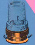
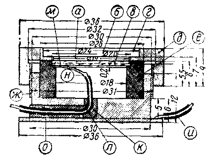
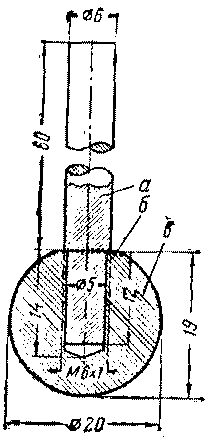
The high-frequency inductor is wound on a ceramic or plastic frame with a diameter of 30 mm with a PELSHO-0,25 mm wire. Winding is carried out in bulk in sections of 100 turns each. In total, the throttle has 300-500 turns. In this design, a self-made power transformer is used, made on a core of Sh-33 plates, the thickness of the set is 33 mm. The network winding contains 544 turns of PEL-0,45 wire. The network winding is designed to be connected to a network with a voltage of 127 V. In the case of using a network with a voltage of 220 V, the winding I must contain 944 turns of PEL-0,35 wire. The step-up winding has 2980 turns of PEL-0,14 wire and the filament winding of the lamps has 30 turns of PEL-1,0 wire. Such a transformer can be replaced by a power transformer of the ELS-2 brand, using only the mains winding, the filament winding of the lamps and the step-up winding completely, or by any power transformer with a power of at least 70 VA and with a step-up winding, providing at a load of 470 V at the anodes of 6PZS lamps. The quartz holder is made of bronze according to the drawing placed in fig. 4. In the case, using a drill with a diameter of 3 mm, an L-shaped hole is drilled to lead out the wire l. A rubber ring e is inserted into the case, which serves to cushion and isolate the quartz. The ring can be cut out of a regular pencil eraser. Contact ring b is cut out of brass foil 0,2 mm thick. This ring has a tab for soldering the wire. Both wires l and and must have good insulation. The wire and is soldered to the support flange O. It is not recommended to twist the wires together.
The lens vessel consists of a cylinder e and an ultrasonic lens b (Fig. 5). The cylinder is bent from a 3 mm thick plexiglass plate on a round wooden template 19 mm in diameter.
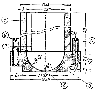
The plate is heated over a flame until softened, bent according to a pattern and glued together with vinegar essence. The glued cylinder is tied with threads and left to dry for two hours. After that, the end ends of the cylinder are aligned with sandpaper and the threads are removed. To manufacture an ultrasonic lens b, you need to make a special device (Fig. 6) from a steel ball with a diameter of 18-22 mm from a ball bearing. The ball should be annealed by heating it to a red heat and slowly cooling it down. After that, a hole with a diameter of 6 mm is drilled in the ball and an internal thread is cut. To fix this ball in the chuck of a drilling machine, it is necessary to make a rod with a thread at one end from a rod.
A rod with a screwed-on ball is clamped into the machine chuck, the machine is turned on at medium speed and, by pressing the ball into a 10–12 mm thick organic glass plate, the required spherical recess is obtained. When the ball deepens to a distance equal to its radius, the drilling machine is turned off and, without stopping pressing on the ball, it is cooled with water. As a result, a spherical recess of the ultrasonic lens is obtained in the organic glass plate. A square with a side of 36 mm is cut out with a hacksaw from a plate with a recess, the annular protrusion formed around the recess is leveled with fine-grained sandpaper, and the plate is grinded from below so that a bottom 0,2 mm thick remains in the center of the recess. Then the places scratched with sandpaper are polished to transparency and the corners are cut on a lathe so that the spherical recess remains in the center of the plate. From the bottom side of the plate, it is necessary to make a protrusion 3 mm high and 23,8 mm in diameter to center the lens on the quartz holder. Having abundantly moistened one of the end ends of the cylinder with acetic essence or dichloroethane, it is glued to the ultrasonic lens so that the central axis of the cylinder coincides with the axis passing through the center of the lens. After drying, three holes are drilled in the glued vessel for tuning screws. It is best to rotate these screws with a special screwdriver made of ordinary wire 10-12 cm long and 1,5-2 mm in diameter and equipped with an insulating material handle. After the manufacture of these parts and the installation of the generator, you can begin to set up the device, which usually comes down to tuning the L1C2 circuit to resonance with the natural frequency of the quartz. The quartz plate in (Fig. 4) should be washed with soap in running water and dried. The contact ring b is cleaned from above to a shine. Carefully place a quartz plate on top of the contact ring and, after dropping a few drops of transformer oil on the edges of the plate, screw the cover d so that it presses the quartz plate. To indicate ultrasonic vibrations, recesses a and d on the cover are filled with transformer oil or kerosene. After turning on the power and warming up for a minute, rotate the tuning knob and achieve resonance between the oscillations of the quartz plate oscillator. At the moment of resonance, the maximum swelling of the liquid poured into the recess on the lid is observed. After setting up the generator, you can begin to demonstrate experiments.
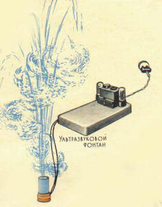
One of the most effective demonstrations is the production of a fountain of liquid under the action of ultrasonic vibrations. In order to get a fountain of liquid, you need to place the "lens" vessel on top of the quartz holder so that no accumulation of air bubbles forms between the bottom of the "lens" vessel and the quartz plate. Then it should be poured into the lens vessel of ordinary drinking water and a minute after the generator is turned on, an ultrasonic fountain will appear on the surface of the water. The height of the fountain can be changed using the adjusting screws, having previously adjusted the generator using capacitor C2. With the correct setting of the entire system, you can get a water fountain with a height of 30-40 cm (Fig. 7).
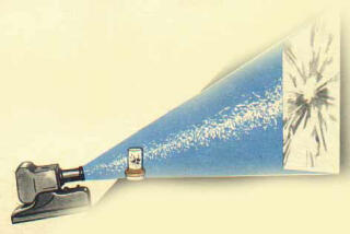
Simultaneously with the appearance of the fountain, a water mist appears, which is the result of a cavitation process, accompanied by a characteristic hiss. If transformer oil is poured into the "lens" vessel instead of water, then the fountain increases noticeably in height. Continuous observation of the fountain can be carried out until the liquid level in the "lens" vessel drops to 20 mm. For long-term observation of the fountain, it is necessary to protect it with a glass tube B, along the inner walls of which the fountain liquid can flow back. When ultrasonic vibrations are applied to a liquid, microscopic bubbles are formed in it (cavitation phenomenon), which is accompanied by a significant increase in pressure at the site of bubble formation. This phenomenon leads to the destruction of particles of matter or living organisms in the liquid. If a small fish or daphnia is placed "in a lens" vessel with water, then after 1-2 minutes of irradiation with ultrasound they will die. The projection of the "lensed" vessel with water on the screen makes it possible to observe successively all the processes of this experiment in a large auditorium (Fig. 8).
Using the described device, it is possible to demonstrate the use of ultrasound to clean small parts from contamination. To do this, a small part (a gear from a clock, a piece of metal, etc.), richly lubricated with grease, is placed at the base of the liquid fountain. The fountain will decrease significantly and may stop altogether, but the contaminated part is gradually cleaned. It should be noted that ultrasonic cleaning of parts requires the use of more powerful generators, therefore, it is impossible to clean the entire contaminated part in a short period of time, and you need to limit yourself to cleaning a few teeth. Using the cavitation phenomenon, an oil emulsion can be obtained. To do this, water is poured into the "lens" vessel and a little transformer oil is added on top. To avoid splashing of the emulsion, it is necessary to cover the lens vessel with the contents with glass. When the generator is turned on, a fountain of water and oil is formed. After 1-2 min. irradiation in the lens vessel, a stable milky emulsion is formed. It is known that the propagation of ultrasonic vibrations in water can be made visible and some of the properties of ultrasound can be clearly demonstrated. This requires a bathtub with a transparent and even bottom and as large as possible, with a side height of at least 5-6 cm. The bathtub is placed above the opening in the demonstration table so that the entire transparent bottom can be illuminated from below. For lighting, it is good to use a six-volt automobile electric light bulb as a point light source for projecting the processes under study onto the ceiling of the auditorium (Fig. 9).
You can also use a regular light bulb of low power. Water is poured into the bath so that the quartz plate in the quartz holder, when placed vertically, is completely immersed in it. After that, you can turn on the generator and, by moving the quartz holder from a vertical position to an inclined one, observe the propagation of an ultrasonic beam in a projection on the ceiling of the auditorium. In this case, the quartz holder can be held by the wires l and c connected to it, or it can be pre-fixed in a special holder, with which you can smoothly change the angles of incidence of the ultrasonic beam in the vertical and horizontal planes, respectively. The ultrasonic beam is observed in the form of light spots located along the propagation of ultrasonic vibrations in water. By placing an obstacle in the path of propagation of the ultrasonic beam, it is possible to observe the reflection and refraction of the beam. The described setup allows for other experiments, the nature of which depends on the program being studied and the equipment of the classroom. Barium titanate plates and, in general, any plates that have a piezoelectric effect at frequencies from 0,5 MHz to 4,5 MHz can be included as a generator load. If there are plates for other frequencies, it is required to change the number of turns in the inductors (increase for frequencies below 0,5 MHz and decrease for frequencies above 4,5 MHz). When altering the oscillatory circuit and the feedback coil to frequencies of 15 kHz, you can turn on any magnetostrictive converter with a power of not more than 60 VA instead of quartz Author: V. Krasnyuk; Publication: N. Bolshakov, rf.atnn.ru
Machine for thinning flowers in gardens
02.05.2024 Advanced Infrared Microscope
02.05.2024 Air trap for insects
01.05.2024
▪ Supercomputer successfully imitates communication with a teenager ▪ Energy Efficient Optical Communication ▪ The glaciers of the Arctic are filled with life
▪ section of the site The most important scientific discoveries. Article selection ▪ article Shcherba Lev Vladimirovich. Famous aphorisms ▪ article Why is it said about a lucky person that he was born in a shirt? Detailed answer ▪ article Common hawthorn. Legends, cultivation, methods of application ▪ article The structure of the jet. physical experiment
Comments on the article: Pazil Very well. Need instruction manual UD-76. Valery How is quartz located in quartz holders, the material of the quartz plate?
Home page | Library | Articles | Website map | Site Reviews
www.diagram.com.ua |


 Leave your comment on this article: