|
|


 Arabic
 Bengali
 Chinese
 English
 French
 German
 Hebrew
 Hindi
Hindi Italian
 Japanese
 Korean
 Malay
Malay Polish
 Portuguese
 Spanish
 Turkish
 Ukrainian
 Vietnamese
|
ENCYCLOPEDIA OF RADIO ELECTRONICS AND ELECTRICAL ENGINEERING Tuning and testing VHF antennas. Encyclopedia of radio electronics and electrical engineering
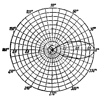
Encyclopedia of radio electronics and electrical engineering / Antennas. Measurements, setup and matching The range of radio communication and the quality of its work depends not only on the correct choice of the type of antennas, but also on the correct configuration of them. This is especially true for the ultrashort wave range, where highly directional antennas are mainly used, which make it possible to significantly increase the range and noise immunity of radio reception. The purpose of this article is to give radio amateurs the necessary information on tuning and testing VHF antennas using simple devices made on their own. In one article it is impossible to consider all types of antennas used by amateurs, so we will try to talk only about vibrator antennas, the installation of which has much in common with the installation of other types of antennas. Main parameters of antennas In amateur practice, when testing antenna-feeder systems, it is enough to take the antenna pattern, measure its gain and check the feeder matching. An antenna pattern is a graphical representation of the relative power or field strength generated by an antenna in different directions and at the same distances from it. Radiation patterns give an idea of the overall radiation pattern of the antenna. On fig. 1 shows an example of constructing in polar coordinates the radiation pattern of a vibrator antenna, consisting of a radiator, a director, and a reflector. The diagram was taken in the horizontal plane of a horizontally located antenna.
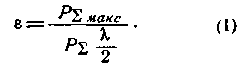
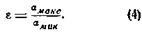
Antenna gain e is a number showing how many times the radiated power of a given antenna in the direction of maximum radiation (PSmax) is greater than the maximum power radiated by a half-wave vibrator (PSl / 2) with the same input power in both cases
It is assumed that the half-wave vibrator is in free space and the power it radiates is equal to the input power.
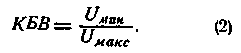
A necessary condition for the normal operation of a receiving or transmitting antenna is the equality of its input impedance to the wave impedance of the supply line and, accordingly, to the input impedance of the receiver or transmitter. If the impedance of the line is not equal to the impedance of the load (the line is not matched), then some of the energy is reflected back from the load, causing the combined wave "incident" from the transmitter to the antenna, a standing wave. By connecting a high-frequency voltmeter to the line and moving it along the line, one can see that the readings of the device periodically change their value (Fig. 2). The coefficient of the traveling wave of the KBV line is determined in this case as the ratio of the minimum reading of the device to the maximum:
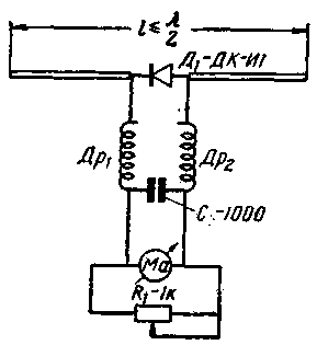
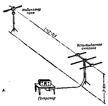
The value of this coefficient characterizes the quality of the feeder. If, for example, the load of the feeder line is short-circuited or disconnected, the CBV is zero. With full agreement, the KBV is equal to one. Measuring instruments The simplest indicators of voltage and current on a feeder or antenna are two lamps - incandescent and neon. So a light bulb from a 3,5 V pocket flashlight and a neon MN-3 give a glow when the power supplied to them is 3-6 watts. To increase the sensitivity of the voltage indicator bulb, a small conductor is sometimes soldered to its base. A necessary device for antenna measurements is a field indicator. It consists of a vibrator, in the gap of which a diode and a device are connected (Fig. 3).
Inductors Dr1 and Dr2 are wound on VS-2 resistances (100 kΩ each) and have 30 turns of PE-0,5 wire wound with variable pitch. For frequencies of 420-435 MHz, these chokes should have 5 turns each. If the sensitivity of the device is not less than 200 μA (frame resistance is about 750 Ohms), and the potentiometer knob is in the position of the smallest shunting of the device, the indicator readings can be considered proportional to the field power. For a correctly executed field indicator, the reception maximum coincides with the direction perpendicular to its middle. In the process of working with the field indicator, the distance between it and the studied antenna is set at least (2,5-3) l. It is advisable to place the tunable antenna and the indicator in an open area free from buildings, forests, etc. (Fig. 4). If the active vibrator of the antenna under test is installed horizontally, the indicator antenna must also be horizontal, and vice versa, if the antenna radiator is vertical, the indicator antenna is placed vertically.
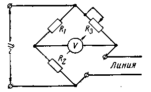
An ordinary bridge can be used to measure the KBV. The measured line is included in one of its arms (Fig. 5).
When the line is matched, the input impedance of the line is equal to the resistance of R3, the resistances of R1 and R2 are the same, the bridge will be balanced. The bridge voltmeter will show zero. However, if the line is not matched, then the bridge will not be balanced. In this case, the scale of the voltmeter can be graduated directly in terms of the coefficient of the traveling wave. The schematic diagram of the bridge is shown in fig. 6.
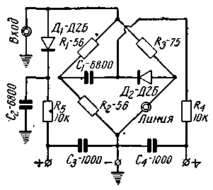
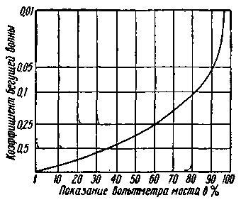
Actually, the bridge here is formed by the resistances R1, R2, R3 and the input resistance of the line, which is connected to the "line" connector. High frequency voltage is connected to the "input" connector. When the voltmeter is connected to the "input" sockets, the input voltage is measured, when the voltmeter is connected to the "line" sockets, the voltage in the diagonal of the bridge is measured. The graduation of the bridge lies in the fact that with the same voltage supplied to it, the voltmeter needle should deviate to the full scale, both with the “line” connector open and closed. If this does not work, it is necessary to select the resistances R1 and R2. Then connect an active resistance equal to the resistance Rs to the "line" connector. Zero voltmeter readings (regardless of frequency) will indicate normal operation of the device. With a high-resistance voltmeter, the reading of the traveling wave ratio will correspond to the graph shown in Fig. 7. The bridge circuit can be used to measure the input impedance of a matched line or the input impedance of an antenna at its resonant frequency. To do this, the resistance R3 must be variable and have a graduated scale. Its value is taken up to 680 ohms, the resistances R1 and R2 each have 240 ohms. When the bridge is balanced, the measured resistance will obviously be equal to R3. When measuring the input impedance of an antenna, in order to exclude the influence of hands, it is necessary to connect the bridge to the antenna through a piece of cable approximately half a wave long.
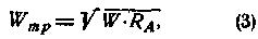
Antenna tuning Regardless of the mode in which the antenna will be operated, it can be tuned and tested both in transmit mode and in receive mode. In practice, it is more convenient to make adjustments in transmission mode. If for this purpose a generator is connected to the antenna feed instead of the receiver, then for a more correct measurement, the value of its output resistance should be the same as the input resistance of the disconnected receiver. If the feeder of the tuned antenna is connected directly to the final stage of the transmitter, then it should be borne in mind that with a strong connection, the transmitter may be detuned and the generator power output during the antenna tuning process will be unstable. To avoid this, it is necessary to carry out tuning, if possible, with a minimum connection between the antenna and the generator, which must have reliable shielding. An antenna can work well, maintaining its characteristics only when it is properly supplied with energy from the transmitter. Therefore, before setting up antennas that require symmetrical power supply, it is necessary to determine the symmetry of the antenna power circuits. This can be done by connecting identical incandescent bulbs to the ends of the dipole. The unequal glow of the bulbs indicates asymmetry, the cause of which is usually the incorrect execution of the balancing device (quarter-wave loop, "U - knee", etc.). Light bulbs are pre-selected so that at the same voltage their glow is the same. Full symmetry is characterized by the equality of voltage and a different phase (opposite of signs) in any section of the wires. After checking the symmetry and eliminating the asymmetry, they proceed to tuning. Tuning the antenna-half-wave vibrator is reduced to adjusting the length of the vibrator. At a certain length of the vibrator, its own resonant frequency becomes equal to the frequency of the transmitter, due to which the power output by the antenna will be maximum. With the help of the field indicator, set in the direction of the greatest radiation of the vibrator (perpendicular to its middle), find such a length at which the readings of the device will be maximum. It is recommended to make the length of the vibrator shorter than the calculated one by 10%, and when setting it up, adjust it more accurately with the help of tubes or nozzles that slide tightly into one another. If the vibrator design does not provide for adjustment, then it is advisable to check its natural frequency. After tuning the vibrator, the feeder matching is checked by measuring the coefficient of the traveling wave. To do this, a bridge is connected to the feeder, at the other end of which the antenna is located. The KBV value for transmitting antennas should be at least 0,5, for receiving antennas at least 0,6-0,8. In the case of a low KBV, it is possible, for example, to connect a matching transformer between the cable and the antenna, which is a piece of cable with a length of about l / 4 where l is the operating wavelength. The wave impedance of this segment Wtr should be equal to
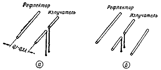
where: W - wave impedance of the feeder, RАis the input impedance of the antenna. After that, the feeder is connected to the receiver (or to the transmitter), the KBV is measured again and, if necessary, matching is performed (a description of various matching devices can be found in the book by Linde D.P. "Antenna-feeder devices" M-L., Gosenergoizdat, 1953 ). After adjusting the feeder, the vibrator, if necessary, is adjusted again. Setting up a two-vibrator antenna with a reflector (Fig. 8, a), start setting up the emitter.
The reflector must be removed when adjusting the emitter. After the emitter and feeder are configured (the configuration method is described above), the reflector is installed and configured. To do this, the field indicator is first installed behind the antenna, against the reflector. By moving the reflector along the antenna or changing its length (or both), one achieves the greatest attenuation of radiation in this direction (backward). Then the indicator is moved in the direction of the main radiation at the same distance from the center of the antenna as in the previous case and the reflector is adjusted in the same way to the maximum radiation (forward). By repeating this operation several times, one strives to obtain the greatest forward radiation compared to backward radiation. For antennas that will work both for transmission and reception, the reflector is fixed in the middle position between the points corresponding to the setting for maximum radiation forward and minimum radiation back. For transmitting antennas, the reflector is left in the position of maximum radiation forward, and for receiving antennas, minimum radiation back. Experience shows that these provisions differ only slightly. When tuned both backwards and forwards, the indicator reading may drop at the same time. This means that the radiated power has decreased due to the strong influence of the reflector on the emitter, which at the same time violates the feeder matching. If it is impossible to adjust the feeder matching, then one should find such a position of the reflector in which the radiation pattern is still satisfactory and the drop in radiated power will not be particularly noticeable. The combination of a good gain in the main direction with a large attenuation of the return radiation is achieved when the distance between the reflector and the emitter is within 0,1-0,3l. Since the elements of the antenna have a great mutual influence, after adjusting the reflector, you need to re-adjust the emitter and feeder. It is much more convenient to work with two field indicators. Having installed one of them from the side of the reflector, and the other from the side of the emitter, they immediately determine the forward-backward ratio by dividing the readings of the indicators. In addition, this makes it possible to exclude the influence of changes in the generator power during measurements and quickly determine the position of the reflector. When setting up a three-element antenna with a reflector and a director (Fig. 8, b), the emitter is also first adjusted. During tuning, its reflector and director are removed or switched off with a special jumper. After adjusting the emitter and matching the feeder, they begin to set up the director, which, just like the reflector, is adjusted to the maximum radiation forward compared to the radiation back. In contrast to the reflector, the length of which increases with adjustment compared to the length of the emitter, the director shortens with adjustment. The director can also be tuned by selecting the distance between it and the emitter. This distance lies within 0,1-0,2l. Next, install and configure the reflector. In the manufacture of antennas, it is useful to provide devices for temporarily turning off reflectors and directors. To do this, these elements are cut in the center and are supplied with short-circuit jumpers. The jumpers must have screws to secure them when the setting is completed. Tuning antennas with a large number of vibrators ("wave channel" type) is similar to tuning a three-element antenna described above. After adjusting the emitter, the first director located near it is adjusted, then the second (without removing the first), the third, and so on. The reflector is adjusted last, which must be turned off or removed when setting up the emitter and directors. In this sequence, these operations are repeated several times. It should be noted that the setup and adjustment of systems with many directors (more than three) is difficult. The radiation pattern of such antennas is very critical to changing the location and length of each director. Antenna tuning in the receive mode is performed using an auxiliary generator with a power of about 1 mW. The generator is loaded on a vibrator, the symmetrical power supply of which is achieved by performing the generator according to a push-pull circuit or by turning on a balancing device. The receiver is connected to the antenna under test. The signal in the receiver is monitored using a microammeter connected in series to the detector load. During measurements, the receiver gain should not be too high. Otherwise, the signal amplitude will be limited and the tuning maximum will not be found. The essence of the tuning method in the receive mode does not differ from the method described above. Those antenna elements that are tuned in the transmit mode to the maximum radiation, in the receive mode are tuned to the maximum of the received signal. By adjusting the reflector or director to the most favorable front-to-back ratio, the generator antenna is placed alternately behind and in front of the antenna at the same distances. Removing Antenna Patterns It is far from always possible to take the full characteristic of the antenna in the range from 0 to 360 °. Judgment on the correctness of the setting can already give a part of the diagram within 30-40 ° to each side of the main beam. The radiation pattern in the horizontal plane can be taken by rotating the antenna under study with a stationary field indicator or by walking around the antenna with the indicator. In the latter case, the indicator is moved exactly along the circle, in the center of which the tuned antenna is located. For ease of reference, the circle is divided by pegs every 10 °. During charting, care must be taken to ensure that the transmitter power remains constant. It is very convenient to carry out such control with the help of the second field indicator, set in the direction of the radiation maximum. The readings of the stationary indicator are recorded simultaneously with the readings of the portable one, and then the readings of the last (portable indicator) are divided by the corresponding readings of the first (fixed) for each direction angle and a diagram is built according to the data obtained. The mismatch of the radiation maximum with the geometric axis of the antenna indicates asymmetry, and a noticeable distortion of the diagram is often due to reflections from foreign objects. For a radiation pattern that characterizes the field in terms of power, the width of the pattern is measured (in degrees) at a level of 0,5 from the maximum (Fig. 1). Gain measurement The antenna under test and the field indicator are positioned in the same way as in the setup process (Fig. 4). The transmitter power is set to such a value that the field indicator needle deviates to the full scale amax. After that, the transmitter is turned off and a semi-wave vibrator is put in place of the measured antenna and connected. Then turn on the transmitter again and note the instrument reading amin. Calculate the gain l of the antenna by the formula
More accurate measurements can be made using a generator that has a calibrated output. By connecting the generator in turn to the antenna under test and the vibrator, the indicator is made to give the same reading in both cases. Then e=Pmax/Pmin, (5) where Pmax is the power of the generator that excites the half-wave vibrator, Pmin is the power of the generator that excites the measured antenna. So, for example, a three-element antenna with a director and a reflector has e=4-6. Author: A. Shur; Publication: N. Bolshakov, rf.atnn.ru
The existence of an entropy rule for quantum entanglement has been proven
09.05.2024 Mini air conditioner Sony Reon Pocket 5
09.05.2024 Energy from space for Starship
08.05.2024
▪ Wind power reaches record 1 TW ▪ 2,5" 3TB Toshiba portable drives
▪ section of the site Tips for radio amateurs. Selection of articles ▪ article Philosophize - the mind will spin. Popular expression ▪ article Why didn't Captain Nemo become a Pole? Detailed answer ▪ article CTO Administrator. Job description ▪ article Fisherman's echo sounder. Encyclopedia of radio electronics and electrical engineering ▪ Aladdin's lamp article. Focus Secret
Home page | Library | Articles | Website map | Site Reviews
www.diagram.com.ua |


 Leave your comment on this article: