|
|


 Arabic
 Bengali
 Chinese
 English
 French
 German
 Hebrew
 Hindi
Hindi Italian
 Japanese
 Korean
 Malay
Malay Polish
 Portuguese
 Spanish
 Turkish
 Ukrainian
 Vietnamese
|
ENCYCLOPEDIA OF RADIO ELECTRONICS AND ELECTRICAL ENGINEERING Antenna on the 33rd television channel. Encyclopedia of radio electronics and electrical engineering
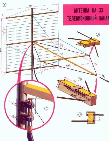
Encyclopedia of radio electronics and electrical engineering / Television antennas The use of the decimeter wave range for television reception provides radio amateurs with ample opportunities for designing various types of antennas. However, due to the characteristics of the propagation of waves in this range, the main attention should be focused on the manufacture of high-performance antennas with narrow radiation patterns. The antenna described in this article belongs to this class. It has a directivity factor (CND) of the order of 50 and is relatively easy to manufacture. It is based on a rhombic canvas, which is well known for its use in the shortwave range. The main disadvantages of a rhombic antenna of the conventional type are reduced efficiency. due to the inclusion of active load resistance and the presence of significant side lobes in the radiation pattern. It is impossible to increase the antenna gain by eliminating the active load and expanding the transverse dimensions of the rhombus wires, since this leads to an additional growth of the side lobes. You can almost completely get rid of the first drawback (i.e., increase the efficiency to about 100%) and significantly weaken the second one (lower the level of side lobes) by loading a rhombic sheet instead of an active, variable reactive load and supplying the antenna with a reflector (Fig. . one).
In this case, the operation of the antenna can be represented as follows: under the action of the exciting emf. an incident wave arises on the wires of the rhombus, propagating towards the reactive load and creating the field Еpad (Fig. 1). Part of the energy of this wave is spent on radiation, and the rest is completely reflected by the reactive load and creates a reflected wave on the wires of the rhombus, propagating towards the screen - reflector. This wave creates a field Eotr. In turn, part of the energy of the reflected wave goes to radiation, and the rest is absorbed by the generator that excited e. d.s. The field of the reflected wave, hitting the reflector, changes the direction of propagation and is superimposed on the field of the incident wave. When the reactive load changes, the superposition conditions change and, as a result, for the resulting field Erez can optimal conditions to be selected. It is obvious that they depend both on the field phase Eop and on its amplitude. The phase of the field Еotr is selected by the reactive load, and the amplitude is set by the diameter of the rhombus wires. In passing, we note that part of the wave energy reflected from the reactive load that enters the feeder can be used to compensate for reflections at its input due to the difference between the feeder impedance and the input impedance of the antenna, which can improve the antenna-to-feeder matching. The conditions for obtaining the optimal resulting field Erez and the feeder operation mode are close to each other, therefore, simultaneously with the desired radiation pattern, antenna matching with the feeder is ensured. The radiation patterns of a rhombic antenna with a reflector and a variable reactive load for l=3L and an angle φ=113° are shown in fig. 2. As can be seen from this figure, for the E-plane (horizontal), the opening angle of the radiation pattern is small (15°). This requires special attention when aligning the antenna.
Structurally, the antenna can be made as shown in Fig.3. It consists of a flat lattice reflector, a rhombic cloth, a power unit and fixing parts (frames and braces). All parts of the reflector, including the mast, can be made of metal. If this is not possible, then the transverse rails 1 of the reflector and the trunk 2 of the mast can be made of wood, and the rest of the parts can be made of wire. It is advisable to pull the ends of the upper and lower transverse rails of the reflector to the mast shaft with braces 3 to prevent sagging of its wires.
Rhombic fabric 4 antennas are made from bare copper wire with a diameter of about 1 mm. It is attached to the ends of the dielectric (wooden) frame. The plane of the frame must be parallel to the plane of the ground and perpendicular to the plane of the reflector. To fix the frame, four braces 5 are used. Both the frame and the braces must be made of a dielectric. For the frame, it is convenient to use ski poles made of bamboo, reed or fiberglass. Braces can be made from several strands of nylon fishing line. If a wooden frame is used, it is necessary to provide inserts made of organic glass in the places of its direct contact with the wires of the rhombic web. All parts of the antenna, with the exception of the assemblies described below, can be made arbitrarily from materials available to the radio amateur. On fig. 3.2 shows the power supply circuit of the antenna. It provides for the transition from a coaxial cable of the RK-75-7-15 (RK-3) type to rhombus wires. This transition (balancing device) is a tube with two grooves. The width of the grooves is 0,4 of the inner diameter of the tube, and the length is about 250 mm. The end of the cable is inserted into the tube from the side opposite the grooves so that its outer braid is stretched over the tube. A bandage is applied over the braid and the tube, braid and bandage are soldered. Then the bare part of the braid and the bandage are wrapped with insulating tape. The polyethylene insulation extended from the second end of the tube (from the side of the grooves) is cut off and the latter is soldered to one of the halves of the tube formed after cutting the grooves. The wires of the rhombic web are soldered to both halves of the tube and the resulting assembly is strengthened directly on the mast shaft, since it has a large load - the tension of the rhombus wires. Before soldering the rhombus conductors to the halves of the tube, a metal ring (a mobile short circuit) is tightly put on it, short-circuiting the halves of the tube and allowing you to change the length of the grooves from the rhombus feed points to the ring. The tube should be attached along the mast shaft on dielectric spacers (textolite, organic glass) so that there is a clearance of 20-30 mm between the tube and the shaft. You can tie the tube to the mast only with dielectric materials, for example, nylon fishing line. Fastening below the grooves can be done with wire. Plastic, ceramic or glass bushings should be inserted into the ends of the cross rail of the rhombus frame (Fig. 3.3). A rhombus wire is inserted into them. At the vertex opposite to the feed points, the rhombus must be loaded with a variable reactive load. It is a two-wire line closed at one end, formed by the continuation of the sides of the rhombus (Fig. 3.4, a). You should avoid placing this line on a wooden frame. Therefore, the end of the longitudinal rail of the rhombus frame should be made of organic glass or other insulating material. In order to be able to change the length of the line, you need to make and put on it a short-circuit bracket (Fig. 3.4, b). You should start tuning the antenna by gradually changing the length of the two-wire load line by moving the short-circuit ring at the feed points of the rhombus so that the length of the grooves is equal to a quarter of the wavelength (131 mm). It is best to assess the correct tuning of the antenna by the form of its radiation patterns, which should be as close as possible to those shown in Fig. 2. If it is not possible to determine the radiation patterns, then the operation of the antenna is determined by the quality of the image on the TV screen. Since at the beginning of the tuning the short-circuiting bracket of the two-wire line is set arbitrarily, there may be a dip in the direction of the main radiation of the antenna. It is easy to detect by rotating the antenna to the left - to the right by ± 20 ° from the direction to the correspondent. In this case, without directing the antenna to one of the available maxima, you should continue tuning. It is necessary to orient the antenna to the failure and achieve its elimination by moving the short-circuiting bracket along the two-wire line. Having chosen the desired position of the short-circuiting bracket, you need to fix it on the line and adjust the antenna by moving the short-circuiting ring at the antenna feed points up and down from its original position. The dimensions of the described antenna can be changed using the graph in Fig. 4, which shows the dependence of the Frome angle (see Fig. 1) on the length of its side l/L, expressed in wavelengths. This graph allows you to calculate the required frame dimensions for a rhombic web. All other nodes of the antenna do not change, with the exception of the reflector, the transverse rails of which should be somewhat longer than the transverse rail of the rhombus frame.
Author: K. Kharchenko; Publication: N. Bolshakov, rf.atnn.ru
Artificial leather for touch emulation
15.04.2024 Petgugu Global cat litter
15.04.2024 The attractiveness of caring men
14.04.2024
▪ CDT advances P-OLED technology ▪ A floating city will be built in the Pacific Ocean ▪ Controlled Release Fertilizers ▪ Cool Bitts ICEbox kit for immersion cooling experiments
▪ section of the site Cultivated and wild plants. Article selection ▪ article Scale - as printed. Tips for the home master ▪ article Who is the author of the microscope? Detailed answer ▪ article The Economist. Job description ▪ article Mastic for the repair of rubber products. Simple recipes and tips ▪ article Make clothes waterproof. Chemical experience
Home page | Library | Articles | Website map | Site Reviews
www.diagram.com.ua |


 Leave your comment on this article: