|
|


 Arabic
 Bengali
 Chinese
 English
 French
 German
 Hebrew
 Hindi
Hindi Italian
 Japanese
 Korean
 Malay
Malay Polish
 Portuguese
 Spanish
 Turkish
 Ukrainian
 Vietnamese
|
ENCYCLOPEDIA OF RADIO ELECTRONICS AND ELECTRICAL ENGINEERING Indoor antenna Signal 1-12. Encyclopedia of radio electronics and electrical engineering
Encyclopedia of radio electronics and electrical engineering / Television antennas In our country, several types of indoor antennas are produced that provide TV reception in the meter wave range (channels 1-12) at a short distance (up to 20 km) from the transmitting station. They have half-wave linear vibrators of a telescopic design or shortened loop vibrators arranged in a fan-like manner. Typically, such antennas are tuned to the desired channel by changing the length and position of the vibrators each time after switching the channel selector. This is very inconvenient, and viewers often get poor quality images. To eliminate this shortcoming, an indoor television antenna "Signal 1 - 12" has been developed, which does not require any adjustment during operation. Only during the initial installation it must be correctly placed relative to the direction to the television center.
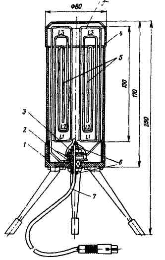
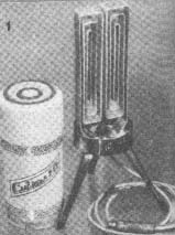
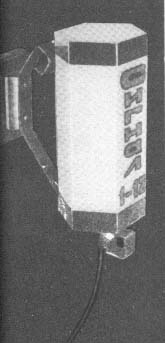
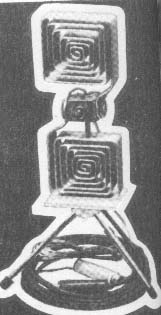
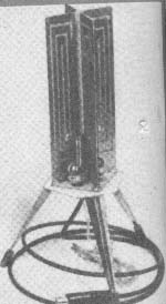
The antenna is made in the form of an electric lamp. A variant of its design is shown in the figure in the text. In addition to three legs, on the base 1 of the antenna, spiral gratings 3 and contact washers 5 are fixed with an insulating sleeve 2 (made of polystyrene, ebonite, etc.) and nuts. The gratings are made of aluminum, copper or brass strip 2 mm thick, 15,..20 mm wide and half the length of the medium wave range (6th channel), i.e. 840 mm. Each of the gratings has three turns, the scan lengths of which, starting from the inner one, are 190, 260 and 390 mm. The pitch of the spiral is taken equal to 10 mm - vertically and 5 mm - horizontally. The lower (in the figure) mounting neck of the insulating sleeve, the holes in the left grille and in the base are square. This is done so that the bushing and gratings do not rotate arbitrarily during assembly and operation. To connect the antenna to the TV, a coaxial cable 7 with a wave impedance of 75 ohms (for example, KPTA), at least 1,6 m long is used. ferrite cores (SSTF). In the figure, the SSTF is "not" shown, and the ends of the cable are soldered to the contact washers. The production and connection of SSTF was described in the article by V. Kuznetsov, V. Paramonov and A. Kukaev "Collective television antennas" ("Radio", 6, No. 1969, pp. 3-26). The antenna arrays are covered with lampshade 4, inserted into the base. The appearance of the antenna assembled and connected to the TV is shown on the 4th p. covers. The considered constructive version of the antenna with the lampshade removed is shown in photo 1 of the cover. The dimensions of vibrator gratings and their arrangement indicated in this variant are not obligatory. Lattices can be made of fiberglass tolite foiled on both sides. Such an antenna provides high-quality TV reception, regardless of its location relative to the direction to the television center. Lattices can be made and placed differently, for example, as in the photo below. The antennas are positioned so that the plane in which the vibrators lie is perpendicular to the direction to the television center. The antenna can be decorated in a variety of ways through the use of a variety of lampshades. They can be made of colored polyethylene, nylon, glass and other opaque materials with a variety of patterns (see pictures at the end of the article). You can also change the configuration of the base. The design of the antenna provides for its placement in both standing and suspended positions. In the second case, the legs are unscrewed from the base of the antenna and screwed to an additional bracket, which is fixed in a place convenient for receiving. In order for the antenna to serve as a night light, 2-4 multi-colored light bulbs are placed in it, having connected the mains voltage to them. When manufacturing an antenna for reception in a different wave range or part of the channels in the range, it must be tuned by changing the size of the gratings and determining the optimal length of the strip sweeps and turns. To receive TV programs at a greater distance from the TV center, it is recommended to mount an amplifier on one transistor in the antenna, for example GT329B. The amplifier can be powered from the TV power supply via a coaxial cable similar to the amplifier discussed in the article by N. Genshenza, V. Kolomiets and N. Savenko "Antenna amplifier with remote tuning" ("Radio", 1975, No. 4, p. 15, 16) . To control the operation of the amplifier, a light bulb is installed on the base, connected to the ends of the coaxial cable. The hole behind which the bulb is located is closed with a cap made of colored transparent plastic.
Author: V.Gurgal, Lviv; Publication: N. Bolshakov, rf.atnn.ru
Artificial leather for touch emulation
15.04.2024 Petgugu Global cat litter
15.04.2024 The attractiveness of caring men
14.04.2024
▪ iiyama T2234MC Professional Monitor ▪ The colonization of Mars will begin with caves
▪ section of the website Audiotechnics. Article selection ▪ article Passive tone controls. The art of audio ▪ article What is anxiety neurosis? Detailed answer ▪ article Clearing railroad switches from snow. Standard instruction on labor protection
Home page | Library | Articles | Website map | Site Reviews
www.diagram.com.ua |


 Leave your comment on this article: