|
|


 Arabic
 Bengali
 Chinese
 English
 French
 German
 Hebrew
 Hindi
Hindi Italian
 Japanese
 Korean
 Malay
Malay Polish
 Portuguese
 Spanish
 Turkish
 Ukrainian
 Vietnamese
|
ENCYCLOPEDIA OF RADIO ELECTRONICS AND ELECTRICAL ENGINEERING Transverter for 50...51 MHz. Encyclopedia of radio electronics and electrical engineering
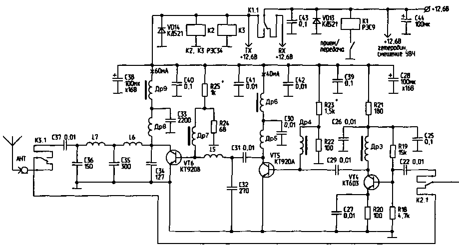
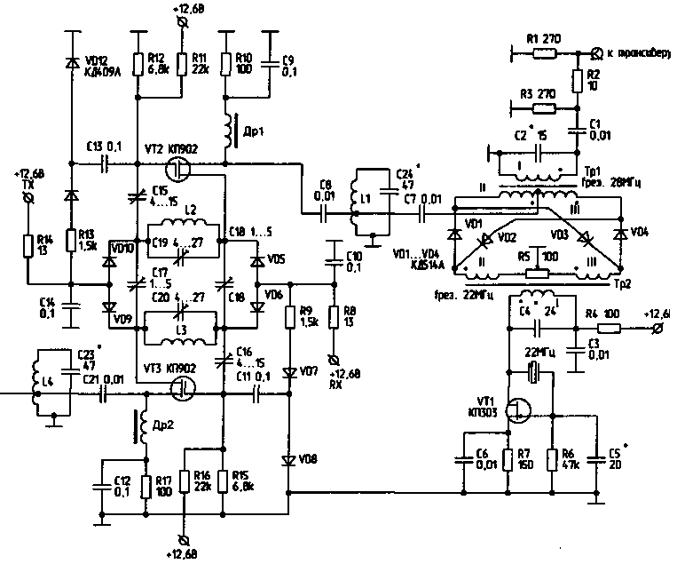
Encyclopedia of radio electronics and electrical engineering / Civil radio communications Since modern transceivers have a sensitivity in the range of 28 ... 30 MHz no worse than 0,25 μV, there is no need to make the gain of the receiving part of the set-top box more than 10 dB. Together with the transceiver, the overall sensitivity in the range of 50 ... 51 MHz will be no worse than 0,1 μV, with a sufficient dynamic range. The transverter has the following parameters: - Gain in the receive mode - 10 dB; Schematic diagram transverter is shown in Fig.1. It is based on the original scheme of a highly dynamic reversing amplifier, successfully used in various transceiver structures. The reversing amplifier in this circuit has a gain of 20 dB in both directions. The attenuation of the signal in the passive mixer and attenuator is 10 dB, so the remaining 10 dB is sufficient for high frequency amplification. In principle, the amplifier allows you to get a gain of up to 40 dB, for this it is necessary to raise the supply voltage to the maximum passport value (for KP902 it is 50 V), respectively changing the bias voltage at the gates to obtain a drain current in the limit of 120 mA. If small circuits with a low quality factor are used, the divider resistors (in the R12, R15 circuit) must be increased in order to obtain the necessary gain. The amplification of the circuit depends on their size and shunting effect on the oscillatory system. But, as in any business, you need to get what you need, and the excess will not do any good.
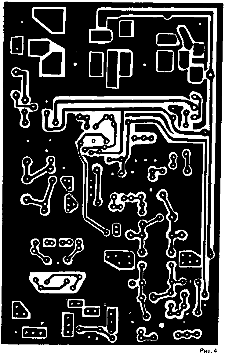
Circuit operation In the "Reception" mode, the signal from the antenna jack through the contacts of the relay K3, K2 is fed to a single circuit L4, C23, which performs preliminary selection in the 50 MHz range. From the loop, the signal is fed to a reversing amplifier, which uses a two-loop FSS. From the output of the amplifier, the signal is fed to the diplexer circuit - L1, C24. In the "Receive" mode, it increases the overall selectivity of the set-top box and matches the output impedance of the amplifier with the input impedance of the mixer. Then the signal is fed to the mixer VD1...VD4, which is made according to the scheme of a double balanced mixer. The output circuit Tr1 is set to the middle of the 28 MHz range. The signal is then sent to the transceiver. The 22 MHz crystal oscillator (VT1) is assembled according to the well-proven Pierce scheme. This generator provides low harmonic content and sufficient output signal amplitude. The oscillatory circuit of the generator consists of C4 and the primary winding of the mixer transformer Tr2. In the "Transmit" mode, the signal from the transceiver, with an amplitude of not more than 0,5 V, is fed to the input of the transverter. Through the attenuator R1, R2, R3, the signal is fed to the mixer. As a result of adding the frequency of 28 ... 29 MHz with the frequency of the crystal oscillator 22 MHz, we obtain a signal in the range of 50 ... 51 MHz. From the output of the mixer, the signal is fed to the circuit L1, C24, which matches the mixer with a reversible amplifier and performs a preliminary selection of the signal. Then the signal is amplified by a reversing amplifier at VT2, VT3, and from the circuit L4, C23, the signal is fed through the contacts of relay K2.1 to the input of the power amplifier VT4 ... VT6. From the output of the power amplifier, the signal through the contacts of the KZ.1 relay enters the antenna. The power amplifier works stably. Winding data: Tr1 and Tr2 are both wound on the SB-12 core. Windings: I - 9 turns, II - 4 turns, III - 4 turns, wire - PELSHO 0,29. Loop coils L1...L7 are frameless. L1, L4 are wound on a mandrel with a diameter of 6 mm with PEL wire 0,8 (9 turns), tap from 3 turns; L2, L3 - on a mandrel with a diameter of 10 mm with PEL wire 0,8 - 7 turns; L5 - on a mandrel with a diameter of 6,4 mm with a PEL wire 0,33 - 1 turn; L6 - on a mandrel with a diameter of 6,4 mm with a PEL wire 0,8 - 1 turn; L7 - on a mandrel with a diameter of 5 mm with a PEL wire of 0,8 - 5 turns. Dr1, Dr2 - type DM with an inductance of 30 μH; Dr3 - type DPM with an inductance of 3 μH; Dr4, Dr7 are wound on a ferrite ring K10x6x4 600 ... 1000 NN, 4 turns of PEL 0,29; Dr5, Dr 8 - on the MLT 0,5 resistor at 180 Ohm, 12 turns of PEL 0,29; Dr6 - Dm0,4, 20 μH; Dr9-Dm3, 12 µH. In the absence of these chokes, you can use any cores of standard chokes, after winding the winding and winding a new one with the required inductance. Setting First, by selecting the capacitance C4 and rotating the core Tr2, it is tuned to the output circuit of the crystal oscillator having a frequency of 22 MHz. Having achieved the maximum amplitude on the winding II or III of the transformer T2, by selecting the capacitance C5, an RF voltage of 0,5 V is set. The tuning resistor R5 achieves a maximum frequency suppression of 22 MHz on the capacitor C7. Turning off the power to the generator circuit by soldering one of the terminals of the resistor R4, selecting the capacitance C2 and rotating the core Tr1, tune the I Tr1 winding to a frequency of 28,5 MHz. Then the reversing amplifier is adjusted. This requires any ICH. Capacitors C21 and C8 are soldered from the circuits L4, C23 and L1, C24, respectively, instead of them, resistors of 100 ohms are soldered, the frequency response is connected and, accordingly, the required voltage RX or TX +12,6 V is applied. Initially, trimmer capacitors C15, C16 are placed in the middle position , and by selecting the capacitance of capacitors C19, C20 and the capacitance of the coupling capacitor C18 (initially setting it to the minimum capacitance position), the required frequency response of the FSS is set, also achieving maximum gain and the maximum possible plane of the top of the frequency response with capacitors C15 or C16. Then they swap the input and output of the IFC on the amplifier, apply a voltage corresponding to either TX or RX, and make a slight adjustment of the FSS in the reverse mode. First, the circuit L4, C23 is soldered, and in the TX mode they are tuned to resonance, then in the RX mode the circuit L1, C24 is soldered and it is also tuned to resonance (by soldering the 100 Ohm resistors, respectively). The power amplifier requires practically no tuning, except for adjusting the quiescent current of transistors VT5, VT6 with resistors R23 and R25, respectively. Design The transverter is made on one printed circuit board (Fig. 4) from double-sided foil fiberglass. On one side, a printed circuit is made, and the second is used as a metal screen. After the final adjustment, fiberglass strips are soldered on all four sides, and a box is made. All parts, except for those related to the power amplifier, are mounted on the side of the solid foil (the holes for the leads are countersinked), as shown in Fig.2. The power amplifier is installed from the side of the printed conductors (Fig. 3) of the printed circuit board, on the other hand, a radiator for power amplifier transistors is installed. Connectors for СР50, ANT and transceiver are brought to the side surface. On the other hand, a supply voltage of +12,6 V and a receive-transmit control signal are supplied through the feed-through capacitors. Author: V.Lazovik (UT2IP), Makeevka; Publication: N. Bolshakov, rf.atnn.ru
Machine for thinning flowers in gardens
02.05.2024 Advanced Infrared Microscope
02.05.2024 Air trap for insects
01.05.2024
▪ Samsung has released a mobile phone with a hard drive ▪ Carbon capture system on tankers ▪ The meaning of life helps to sleep peacefully
▪ section of the site Normative documentation on labor protection. Article selection ▪ article Friends in need are known. Popular expression ▪ article Functional composition of Rolsen TVs. Directory ▪ article How to wind the speedometer. Encyclopedia of radio electronics and electrical engineering ▪ Dinistors article. Encyclopedia of radio electronics and electrical engineering
Home page | Library | Articles | Website map | Site Reviews
www.diagram.com.ua |

 Leave your comment on this article: