|
|
ENCYCLOPEDIA OF RADIO ELECTRONICS AND ELECTRICAL ENGINEERING Dual tone multi-frequency (DTMF) generator on the AVR. Encyclopedia of radio electronics and electrical engineering
Encyclopedia of radio electronics and electrical engineering / Telephony Otherness
Introduction This document describes how to generate DTMF (Dual Tone Multi-Frequency) signals using any AVR microcontroller containing a Pulse Width Modulation (PWM) block and SRAM. These signals are widely used in telephony, where they are played when you press the dialing buttons of the telephone set. To correctly generate a DTMF signal, two frequencies must be superimposed together: a low frequency (fb) and a high frequency (fa). Table 1 shows how different frequencies are mixed to produce DTMF tones when different keys are pressed.
Table 1. Tone Shaping Matrix
The rows of Table 1 represent low frequency values, and the columns show high frequency values. For example, the matrix shows that pressing the button "5" should mix the frequencies fb = 770 Hz and fa = 1336 Hz. As a result of the addition of two sinusoidal signals of different frequencies, a DTMF signal is formed
where the ratio of amplitudes K=Ab/Aa source signals must meet the condition
Operating principle In addition to general information about the use of pulse-width modulation, the following will show how pulse-width modulation allows you to generate sinusoidal signals. The following paragraph describes how to obtain different frequencies using the base PWM frequency. After considering the theoretical foundations, a description of the DTMF signal generator itself will be given. Generation of sinusoidal signals Depending on the ratio of the duration of the high VH and low VL voltage levels, the average value at the PWM output changes. If the ratio between the durations of both levels is kept constant, then a constant voltage level VAV will be generated as a result. Figure 2 shows a pulse width modulated signal.
The voltage level is determined by the expression:
A sinusoidal signal can be generated provided that the average value of the voltage generated by the pulse width modulation will change every PWM cycle. The ratio between high and low levels must be set according to the voltage level of the sinusoidal signal at the corresponding time. Figure 3 illustrates this process. The initial data for PWM are calculated for each of its periods and recorded in the conversion table (TP). Figure 3 also illustrates the relationship between the frequency of the fundamental sine wave and the number of samples. The higher the number of samples (Nc) - the higher the modeling accuracy of the resulting signal:
The PWM frequency depends on the PWM resolution. With 8-bit resolution, the end value (top of count) of the timer is 0xFF (255). Because timer counts up and down, this value must be doubled. Therefore, the PWM frequency can be calculated by dividing the timer clock fCK by 510. Thus, with a timer clock frequency of 8 MHz, the resulting PWM frequency will be 15.6 kHz.
Changing the frequency of a sinusoidal signal Assume that the sinusoidal samples are read from the lookup table not sequentially, but one at a time. In this case, at the same sample rate, a signal with a double frequency will be generated (see Figure 4).
By analogy, if you read not every second value, but every third, fourth, fifth (respectively, the step width is 3, 4, 5 ...), etc. it is possible to generate Nc-frequencies in the range [1/T Hz .. 0 Hz]. Note that for high frequencies the resulting waveform will not be sinusoidal. The step width according to the conversion table is denoted as XSWWhere
Calculation of the current position in the TP for the next PWM period (when the timer overflows) is performed using expression (6). New value at X positionLUT depends on its previous state at position X'LUT with the addition of step width XSW
Adding different frequencies to get a DTMF signal The DTMF signal can be generated using expressions (1) and (2). For simplicity of arithmetic operations, the value of the coefficient K is taken equal to 0.75 in order to replace the arithmetic operation with logical shifts. Taking into account expression (6), the current value for PWM control can be calculated by the expression:
and taking into account that XLUTa=X'LUTa + XSWa,XLUTb=X'LUTb + XSWb, we finally write
Implementing a DTMF Generator This appendix discusses building a DTMF tone generator using an 8-bit PWM output (OC1A) and a table of 128 sine function samples (Nc), each specified by 7 bits (n). The following expressions show this dependency and also show how to calculate the elements of the lookup table:
The advantage of using 7 bits is that the sum of the high and low frequency signal values is one byte in size. To support the full set of DTMF tones, 8 values for each DTMF frequency from Table 1 must be calculated and entered into a conversion table. To achieve higher precision, the following solution was made: the values calculated by expression 5 require only 5 bytes. To use all 8 bytes, which will reduce the rounding error, this value is multiplied by 8. A pointer to the conversion table is written in the same way. But in this case, it takes two bytes to store 8 times the value. This means that 3 right shifts and an Nc base modulo operation (logical multiplication by Nc-1) must be performed before using these bytes as a pointer to sinusoid values in
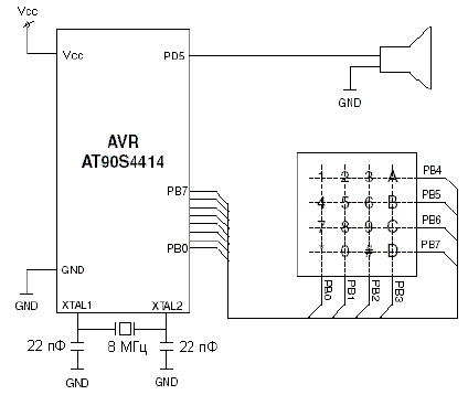
The PWM signal is generated at the OC1A (PD5) pin. An additional output filter will help to better match the sinusoidal waveform. As the PWM frequency decreases, it may be necessary to use a filter with a steeper frequency response to obtain a good result. The connection of the keyboard is shown in Figure 1. The operation of the keyboard must be organized in such a way that it is possible to determine the pressed key. This can be done using the following algorithm:
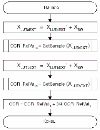
Note: The STK200 has resistors in series between the PORTB connector pins and the microcontroller pins BP5, PB6, and PB7 (see the STK200 schematic). This will cause problems if a keyboard is connected to the PORTB connector. Figure 6 illustrates the operation of the subroutine for determining the pressed key. Depending on the key pressed, the duration of the interval is determined. The interrupt routine uses this value to calculate the PWM settings for the two DTM tone sine waves. The interrupt handling procedure is shown in Figures 7 and 8. This routine calculates a value to compare with the timer output for the next PWM period. The interrupt routine first calculates the position of the next sample value in the lookup table and reads the value stored there. The position of the sample in the lookup table is determined by the pulse duration, and the actual pulse duration is determined by the generated frequency. The final value, which is written to the timer comparison register, is determined using formula (7), which takes into account the sample values of both DTMF frequencies.
Publication: cxem.net
Artificial leather for touch emulation
15.04.2024 Petgugu Global cat litter
15.04.2024 The attractiveness of caring men
14.04.2024
▪ Jupiter diverts comets and sends asteroids to Earth
▪ site section Power Amplifiers. Article selection ▪ article Venereal disease. Basics of safe life ▪ article What is in the US area, the area code of which is 321? Detailed answer ▪ article Specialist in foreign economic activity. Job description ▪ Article Optocouplers. Part 2. Encyclopedia of radio electronics and electrical engineering
Home page | Library | Articles | Website map | Site Reviews www.diagram.com.ua |


 Arabic
 Bengali
 Chinese
 English
 French
 German
 Hebrew
 Hindi
Hindi Italian
 Japanese
 Korean
 Malay
Malay Polish
 Portuguese
 Spanish
 Turkish
 Ukrainian
 Vietnamese

 (1)
(1) (2)
(2)
 (3)
(3) (4)
(4)

 (5)
(5) (6)
(6) (7)
(7) (8)
(8) (9)
(9) (10)
(10)


 Leave your comment on this article: