|
|


 Arabic
 Bengali
 Chinese
 English
 French
 German
 Hebrew
 Hindi
Hindi Italian
 Japanese
 Korean
 Malay
Malay Polish
 Portuguese
 Spanish
 Turkish
 Ukrainian
 Vietnamese
|
ENCYCLOPEDIA OF RADIO ELECTRONICS AND ELECTRICAL ENGINEERING Power indicators for electric soldering irons. Encyclopedia of radio electronics and electrical engineering
Encyclopedia of radio electronics and electrical engineering / Ham Radio Technologies Almost all electrical and electronic devices powered by a 230 V mains supply are equipped with indicator lights for the on state. It is not uncommon for electrical appliances left unattended to cause a fire. The presence of light indicators of inclusion allows you to control their status and, in most cases, prevent the unpleasant consequences of forgetfulness. Nevertheless, there is a whole class of electric heaters that are not equipped with such indicators. This is one of the main tools of a radio amateur - electric soldering irons. In the article brought to the attention of readers, the author tells how to embed the on-state indicator light into soldering irons designed for power supply from several units to 230 V. When assembling electronic structures or dismantling radio components from printed circuit boards, sometimes you have to use several electric soldering irons of different capacities, keeping some of them on all the time, turning on others from time to time if necessary. In order to know at any time what condition a particular soldering iron is in, they can be equipped with simple light indicators. The main problem here is where to place the indicator. On fig. 1 shows a diagram of an indicator in which a glow discharge lamp is used. This device is designed for electric soldering irons powered by 230 V AC. Indicator lamp HL1 and current-limiting resistor R1 are installed inside the case of a collapsible handle of a "Chinese" soldering iron with a power of 40 W (real - 30 W), combined with vacuum solder suction (Fig. 2 ). The HL1 lamp is a miniature (3 mm in diameter and 8 mm long) gas-discharge lamp used in imported rocker (keyboard) switches (voltage - about 60 V, glow color - orange). A rubber orange light filter from incandescent lamps 12 V 40 mA, used in imported car radios, is put on its glass cylinder and glued with cyanoacrylate glue. The lamp with a light filter is partially exposed to the outside, for which a hole with a diameter of 4,5 mm is drilled in the handle body. Inside the handle, the lamp and the resistor were first glued with cyanoacrylate glue, then, after a few hours, with Quintol-Lux synthetic glue. The glow of this lamp is clearly visible even against the backdrop of very bright workplace lighting.
On fig. 3 shows a diagram of an indicator for electric soldering irons with an operating voltage of 36, 40 or 42 V. The function of the indicator itself is performed by a small-sized (length without brass contacts - 32 mm) incandescent signal lamp for a rated voltage of 60 V and a current of 50 mA. It is difficult to mount such a lamp in the handle of an electric soldering iron, so it is placed in a piece of a translucent plastic case from a felt-tip pen, put on the power cord a few centimeters from the soldering iron handle (Fig. 4). Instead of the specified lamp, you can use any other with close values of operating voltage and current (for example, 48 V and 60 mA). The peculiarity of such an indicator is that its glow is clearly visible from any viewing angle.
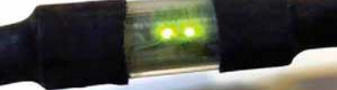
On fig. 5 shows a diagram of an LED indicator designed for an operating voltage of 12 V. The device can operate when the soldering iron is powered by both direct and alternating current. LEDs HL1 - HL4 - SMD-version, green glow, connected in pairs in anti-parallel. Together with current-limiting resistors R1 and R2, they are mounted on a printed circuit board with dimensions of 22x3 mm (Fig. 6) made of double-sided foil fiberglass 1 mm thick (LEDs are installed in pairs on its different sides). The indicator is mounted in a 29 mm long section of a transparent plastic case from a "school" ballpoint pen 9 mm in diameter (Fig. 7).
By installing current-limiting resistors in proportion to a smaller or larger resistance, such an indicator can be used in electric soldering irons designed for an operating voltage of 6 or 24 V. For a more even distribution of the generated heat, two identical current-limiting resistors are installed inside the indicator housing instead of one larger resistance. The scheme of the LED indicator for turning on the soldering iron, designed to operate from an AC voltage of 230 V, is shown in fig. 8. LEDs HL1, HL2 are connected in anti-parallel, the current through them is limited by resistors R1, R2. The device is mounted in a thin mains plug (Fig. 9). To avoid its noticeable heating, super-bright yellow SMD LEDs were used (used in the car radio to illuminate the buttons). The average current through the LEDs is about 640 μA at a mains voltage of 230 V. The total resistance of the resistors R1, R2 is chosen in such a way as to avoid damage to them and the plug housing at voltages up to 420 V.
Before installation, segments of a thin stranded mounting wire in fluoroplastic insulation are carefully soldered to the LEDs (it will not be easy to do without a special device). The resistors are soldered to the brass contacts of the mains plug, the LEDs are installed in holes drilled from different sides of the plug. From the inside they are glued with Quintol-lux glue, outside - with cyanoacrylate or transparent epoxy glue. The leads of the resistors with the wires soldered to them are glued to the body of the plug with BF glue. The glow of the crystals of these LEDs is also clearly visible even in very bright workplace lighting. All photos show indicators in working order. To fix the position of the indicators on the soldering iron power cords, white or transparent ethylene vinyl acetate glue is used. Heat-shrinkable tubes of the appropriate diameter were used to isolate the connections and additionally fix the indicator units. When equipping soldering irons with the indicators described, it is also advisable to put two or three pieces of a heat-shrinkable tube of a slightly larger diameter on the power cord, but do not heat treat them. This will allow, if necessary, to easily repair a damaged power cord, which often happens during the operation of electric soldering irons. In conclusion, it should be noted that instead of self-made indicators, you can use luminous wires with built-in LED backlighting to signal the inclusion of soldering irons, if you replace the power wires with them. Author: A. Butov
Artificial leather for touch emulation
15.04.2024 Petgugu Global cat litter
15.04.2024 The attractiveness of caring men
14.04.2024
▪ Small insects do not try to mimic perfectly ▪ Playing with other children affects language learning ▪ MAX9730 Class G Audio Power Amplifier
▪ site section Tone and volume controls. Article selection ▪ article Striga under Kotovsky! Popular expression ▪ article Where is the center of mass of the Earth-Moon system? Detailed answer ▪ article Ionizing radiation and protection against them ▪ article Knots of amateur radio equipment. Miscellaneous. Directory ▪ article Effective switching regulator. Encyclopedia of radio electronics and electrical engineering
Home page | Library | Articles | Website map | Site Reviews
www.diagram.com.ua |


 Leave your comment on this article: