|
|


 Arabic
 Bengali
 Chinese
 English
 French
 German
 Hebrew
 Hindi
Hindi Italian
 Japanese
 Korean
 Malay
Malay Polish
 Portuguese
 Spanish
 Turkish
 Ukrainian
 Vietnamese
|
ENCYCLOPEDIA OF RADIO ELECTRONICS AND ELECTRICAL ENGINEERING Stand-regulator for soldering iron. Encyclopedia of radio electronics and electrical engineering
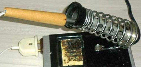
Encyclopedia of radio electronics and electrical engineering / Ham Radio Technologies The author not only made an automatic machine that regulates and stabilizes the operation of the soldering iron, but also placed it in the "basement" of the soldering iron stand, saving space on the desktop. The long-standing sad experience of using a 230 V soldering iron, when a breakdown of the insulation between its heater and the tip made the expensive measuring device being repaired completely unusable, made me reconsider my attitude to soldering equipment. Since then, I have only used 36V soldering irons, powered by a reliable isolating transformer. Depending on the size and weight of the soldered components, I had to use several soldering irons of different power. The use of soldering stations was constrained by their large dimensions and, of course, cost. There were attempts to turn on the only soldering iron through a trinistor regulator in order to use only it in various situations, but the annoying hum of the transformer through which the soldering iron was connected to the network forced us to look for a different solution to the problem. There was no difficulty in choosing a soldering iron, because all that I had were only 36 V. The design was based on a convenient soldering iron stand available for sale (Fig. 1), in which I tried to rationally use the empty space of the "basement ".
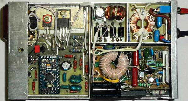
It turned out to be an easy-to-use universal stand-regulator for soldering irons with a power of up to 40 W for a voltage of 36 V. The principles laid down in it can also be used for soldering irons for a different voltage by replacing some components, changing the winding data of the chokes, and also correcting the program. To power the soldering iron, a modified "electronic transformer" for TRS 60W halogen lamps (Fig. 2), purchased from an electrical goods store, was used. As a result, it was necessary to solve the problem of reducing interference and pay special attention to electrical safety.
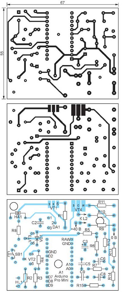
I have been using microcontrollers for a long time, but this time I used the Arduino Pro Mini module with an ATmega328A microcontroller and a 16 MHz quartz resonator, as well as the Arduino IDE program development environment designed for it, to control the soldering iron and regulate its heating. The developed program allows you to select five operating modes of the soldering iron by pressing the button and maintain the selected mode, automatically correcting the instability of the mains voltage. Using the same soldering iron, mode 1 can be used to work with low-melting solders, for example, Wood's alloy, and mode 5 allows even massive components to be heated normally. The regulation principle is based on the formula for determining the current power of the soldering iron heater P = Iн2Rн, where Rн - heater resistance; Iн - the current value of the current through it. Each time the device is turned on, it measures the resistance of the soldering iron heater and calculates its power at a voltage of 36 V, on the basis of which it sets the power for each of the five modes: 20% - for mode 1; 40% - for mode 2; 60% - for mode 3; 80% - for mode 4; 100% - for mode 5. The schematic diagram of the regulator is shown in fig. 3. The heating power is controlled by feeding the soldering iron with rectangular pulses of adjustable duty cycle, following at a frequency of about 500 Hz. A field-effect transistor VT4 is used as a power switch, the feature of which is a rather large gate-source capacitance. To reduce the dragging of the control signal drops caused by the recharging of this capacitance, which leads to an increase in the power dissipated by the transistor VT4, transistors VT2 and VT3 are designed.
The pulses from the output D9 of the Arduino module through the resistor R3 control the transistor VT2. A high logic level opens this transistor, which quickly discharges the gate-source capacitance of the transistor VT1 through the VD4 diode and closes it. At the same time, the transistor VT3 will also be closed. A low logic level from the output D9 will close the transistor VT2, and the transistor VT3 will be opened by the current flowing through the resistor R8. Transistor VT3 - an emitter follower with low output resistance - quickly charges the gate-source capacitance of transistor VT4 and opens it. The D8 Arduino output is used to control the HL1 LED, which displays the current mode of operation of the regulator and serves as an indicator of emergency situations. At the output of D7, Arduino generates sound signals applied to the HA1 piezoelectric element. Input D2 is used to poll the state of the button SB1. When it is released, the software-enabled internal resistor of the microcontroller maintains a high logic level at this input. Pressing the button lowers the level. To measure the current flowing through the soldering iron, and the voltage from which the device generates a pulse sequence supplied to the soldering iron, the analog inputs of the Arduino module A0 and A1 were used. The impulse voltage, proportional to the current of the soldering iron, is removed from the resistors R9-R11. The R14C8R15C9 filter extracts from it a constant component proportional to the average value of this current. It goes to input A0. To measure the supply voltage, a voltage divider R12R13 with a smoothing filter C6R7C5 was used, the constant voltage from which is fed to input A1. The Arduino module and the VT4 transistor control unit are powered by +9 V from the stabilizer on the DA1 parallel integrated regulator and the VT1 transistor. Of course, it would be more correct to use a transformer with a secondary winding for the required voltage and with a rectifier. But for the sake of simplicity, the +9 V voltage is derived from the soldering iron supply voltage. It must be admitted that in this case, the transistor VT1 turned out to be the most powerful source of heat in the device. The mains cord, as well as the soldering iron cord, are good antennas, capable of emitting a wide range of interference generated by the voltage converter in the "electronic transformer" U1. To reduce the noise level, partial shielding of individual nodes was used, and three common-mode noise suppression filters were used on two-winding chokes L1-L3. The first filter C1L1C4 prevents the penetration of interference into the mains. Choke L2 is installed directly at the outlet to which the soldering iron is connected. Filter L3C7 reduces the level of interference after the rectifier. A valuable property of such filters is that they, without having any effect on the operating differential (asymmetric) voltage and current, well attenuate common-mode (symmetrical) interference. To use the "electronic transformer" tRs 60W in the regulator, it was required to remake it. The fact is that it uses feedback on the load current, which is good when using the "transformer" for its intended purpose, but not in our case, since such feedback significantly narrows the range of permissible load. With a load of less than 5 ... 6 W, the converter could not work at all without modification. However, a simple alteration gave him the opportunity to work even without a load. All improvements are shown in a simplified diagram (Fig. 4). Chains that need to be removed are marked with crosses on it. Newly added circuits and elements are highlighted in red, and the rewound winding II of transformer T2 is in blue. The numbering of elements on the diagram is conditional and may not coincide with their marking on the device board.
First of all, it is necessary to unsolder the transformer T2 and remove the winding II from it. For greater reliability and increased electrical safety, I recommend applying several layers of insulation from a fluoroplastic film cut into 10 mm wide tapes over winding I, and put thin plastic tubes on the leads of this winding. For the new winding II, I used the MGTF-0,35 wire, which wound 36 turns. To fix the terminals of the secondary winding, it is recommended to put a common heat-shrinkable tube on them and warm it up with a hairdryer. After that, you can solder the transformer into place. A protective resistor R1 was installed at the network input of the converter. It is recommended to install an RK1 thermistor instead, eg S153/10/M or similar. An additional capacitor C1 and resistor R2 can be placed on a small piece of the breadboard by fixing it perpendicular to the main converter board. I did this using a rigid single-core copper wire with a diameter of 1,5 ... 2 mm, soldered to a printed conductor, with which the lower terminal of the capacitor C3 and the emitter of the transistor VT2 are connected. To reduce the size in height, resistor R2 can be made up of three resistors connected in series with a resistance of 2,2 ohms and a power of 1 watt. From the transformer T1, it is necessary to remove the current feedback winding I, which is a coil of wire passed through the window of the magnetic circuit. On the board, instead of this turn, a jumper should be soldered. Make a new feedback circuit from a piece of wire MGTF-0,07. Solder one end of it to the resistor R2, make two turns (winding III) of this wire on the transformer T2, then pass it through the window of the magnetic circuit of the transformer T1 (winding Ia) and solder the wire to the other terminal of the resistor R2. If the converter does not work during the test, remove the winding wire Ia from the transformer T1 and pass it through the magnetic circuit window in the opposite direction.
The body of the device is made of aluminum sheet 1 mm thick according to the sketch shown in fig. 5. The width and height of the case are limited by the internal dimensions of the "basement" of the soldering iron stand, and its length is 10 mm longer than the length of the stand. At the bends in the workpiece, cut grooves, for example, with a cutter from a hacksaw blade. Their depth should be sufficient to bend the sheet manually with some effort. Do not cut too deep, this will degrade the strength of the structure. When marking the development, it must be remembered that on the bends it is necessary to take into account the thickness of the aluminum sheet. In the front (right, according to Fig. 5) part of the case, a shelf 5 mm wide is made, which is 2 mm higher than the rest of it. This shelf is a kind of lock, which includes the front of the stand. In the left, according to the sketch, part of the body, a hole was drilled, in which a captive M2,5 nut was flared in such a way that after installing the front part of the stand in the lock, its rear part blocked the threaded hole of the nut by at least half. In order for the thread to open, opposite the installed nut, a notch is made with a round needle file in the back of the stand. Then the stand is fixed to the body with a screw. In the front wall of the case, holes should be prepared for M3 screws that serve to fasten the converter transistors, for a rubber bushing for the power cord and for the SA1 power switch. Specify the location of the holes and their size locally based on the availability of parts and their design features. In the rear wall of the case, holes must be drilled for the socket for the XS1 soldering iron, the SB1 button and the HL1 LED. Determine the position of the holes for the button and the LED before installing the printed circuit board of the control device into the housing. Install the socket in the upper right (according to Fig. 5) corner of the control device compartment as far as possible from the bottom of the housing, because under the socket there will be a part of the printed circuit board with the HA1 piezoelectric emitter installed on it. I recommend, for safety reasons, to replace the standard soldering iron plug with another one that is incompatible with a conventional power outlet, and on the controller, install the socket corresponding to the new plug as XS1. This will eliminate the possibility of accidentally plugging the soldering iron into the network. Next, make screens from an aluminum sheet about 0,5 mm thick that separate the compartments of the case. Their height should be as high as possible. Bend the lower part of each screen 5 mm wide at a right angle and attach it to the body with countersunk rivets 1,5 ... 2 mm in diameter. The use of rivets is due to the small gaps between the bottom of the case and the undersides of the printed circuit boards. The gaps between the edges of the printed circuit boards and the screens must be at least 1 mm wide so that the insulating boxes made of pressboard can fit into them. At the top, according to Fig. 5, part of the control device compartment, install the aluminum heat sink plate for transistors VT1 and VT4. Its dimensions are 50x20 mm, thickness - 2,5.3 mm. The plate is riveted to the bottom of the housing, after having previously lubricated the contacting surfaces with KPT-8 heat-conducting paste. The appearance of the assembled device (without a soldering iron stand installed on it) is shown in fig. 6.
A drawing of a single-sided printed circuit board for a line filter is shown in fig. 7. Insert a captive nut M1 with a height of no more than 2,5 mm into the hole of large diameter, located under the throttle L3, from the side of the printed conductors and flare. It is designed for a screw that secures the board to the bottom of the case, in which you need to drill a corresponding hole.
For the FU1 fuse insert, install the S1050 holders on the board. Capacitors C1 and C4 - K73-17, inductor L1 is used ready from a faulty device. The inductance of each of its windings is 3,3 mH. I recommend installing mounting racks in the holes for external connections of the board, for example, from pin contacts of PLD or PLS connectors. Before installing the mains filter printed circuit board into the housing, cut out a box blank from a 0,5 mm thick pressboard to fit the housing compartment and fold it. The side walls of the box must be higher than all the elements installed on the board. Such a box is guaranteed to isolate the regulator case from circuits with mains voltage on the board. In the box, you need to make holes in advance for the SA1 switch, the power cord and the board mounting screw. After inserting the box into the compartment, install it in it and fix the printed circuit board from the side of the bottom of the case with a screw. The length of the screw must be such that its end does not protrude above the top surface of the board. Next, install the SA1 switch (I used TNX-01) and a rubber grommet for the power cord. The drawing of the printed circuit board of the rectifier is shown in fig. 8. Printed conductors are available on both sides. Capacitor C7 must be able to pulse at an increased frequency. Therefore, a HITANO EXR capacitor is used here. You can also use an ESG series capacitor or similar capacitors from other manufacturers.
Inductor L3 - from another device with an inductance of each winding of 15 μH. Please note that the windings of this finished inductor are wound in different directions, so they should be connected in strict accordance with Fig. 8. If there is no ready-made choke, it is easy to make it yourself on a suitable ferrite ring magnetic core. The windings are wound with double-folded varnished wire with a diameter of 0,8 mm in one layer until filled. It is advisable to make sure that the inductance of each of the identical windings is at least 15 µH. The above recommendations for installing mounting racks, insulating the board with a pressboard box and fixing it, apply to this board as well. The same box must be made for the "electronic transformer" removed from the case and the modified voltage converter board. The transistors of the converter for cooling will need to be pressed against the front wall of the case through insulating gaskets, so the height of the box wall adjacent to it should be carefully selected. Make the rest of its walls the maximum height. Having temporarily installed the converter board in the compartment intended for it, specify the places where the transistors are pressed to the case. Then install insulating mica plates with a thickness of at least 0,15 mm, previously lubricated with heat-conducting paste, in these places. The dimensions of these plates should be 2 ... 3 mm larger than the corresponding dimensions of the transistor cases. It is necessary to pre-solder the input and output wires to the converter board. Input - MGSHV, output - MGTF-0,35. Having inserted the insulating box into the compartment, install the converter board into it, having previously lubricated the transistors on the side of thermal contact with the case with heat-conducting paste. Then press the transistors against the front of the case with a plastic or metal clamp used in an "electronic transformer". If the clamp is metal, I recommend placing a pressboard gasket under it to prevent the clamp from touching the components on the converter board. The double-sided printed circuit board of the control device is shown in fig. 9. It provides space not for one, as on other boards, but for three captive nuts. It is recommended to flare them before starting the installation of parts, some of which may partially overlap the nuts. After flaring the nuts, using the board as a template, mark and drill the mounting holes in the bottom of the case.
Keep in mind that the Arduino Pro Mini module has a rather high programming connector, and there is a ledge on the bottom surface of the soldering iron stand, which, if the control board is not properly installed, can rest against this connector. To avoid this, you should not only be especially careful when installing the board, but also insert the Arduino module pins as deep as possible into the holes intended for them, and after soldering, cut off the protruding parts of the pins from below. Mount all parts on the board, with the exception of transistors VT1 and VT4, not forgetting that the leads of the parts to which the printed conductors on both sides of the board fit must be soldered on both sides. After installation, specify the position of the holes for the SB1 button and the HL1 LED on the housing wall and drill these holes. When the board is finally installed, a pressboard gasket should be placed under it. After installing the control board, determine the position of the transistors VT1 and VT4 on the heat sink plate and drill holes in it for their fastening. Place a mica gasket under the VT4 transistor and secure it with an M2,5 screw with a nut, putting an insulating sleeve on the screw and placing an insulating washer under the nut. Do not forget to lubricate the gasket with heat-conducting paste. The 2SC3611 transistor was chosen as VT1 because its plastic housing can be attached to the heat sink without additional insulation. However, it is still necessary to apply a heat-conducting paste to the mating surfaces. Solder the conclusions of the transistors fixed on the heat sink to the contact pads intended for them on the control board. To pass the wires between the boards in the screens dividing the compartments, make small cutouts. The wires coming from the control unit board to the XS1 socket must be passed through a ring of size K10x6x4,5 made of ferrite 2000NM1, winding them in two turns. This will be the L2 choke. It remains to connect the power cord. I recommend checking with a multimeter in the resistance measurement mode the correct installation, the absence of electrical connections between the device case and its circuits under mains voltage. It will not be superfluous to control the circuits of the mains voltage and the secondary circuits of the converter for short circuits. In the stand for the soldering iron, it is necessary to replace the bolt connecting its base to the spring with another one with a flatter head. I recommend sticking an insulating overlay made of pressboard on this head. Opposite the center of the transformer T2 of the converter, I recommend gluing a rubber stopper to the base of the stand. It will additionally press the board to the case and suppress its vibration, which can lead to a break in the terminals of the converter transistors mounted on the device case. To upload a program to the Arduino Pro Mini, you need a computer connected to the Internet and a programmer, preferably with a USB interface. Go to http://arduino.cc and download the free Arduino IDE, a programming environment for Arduino. After installing this program on your computer, open the Reg_Sold.ino file attached to the article in it. In the "Tools→Board" menu, select "Arduino Pro or Pro Mini", and in the "Tools→Processor" menu, select "ATmega328 (5V, 16 MHz)". In the menu "Tools→Programmer" it is necessary to choose from the proposed list the programmer that you intend to use to load the program into the module. Start compiling the program by selecting the menu item "Sketch→Check/Compile". After compiling successfully, connect the programmer to the programming connector of the Arduino Pro Mini module and to the USB connector of the computer. The Arduino Pro Mini should turn on LED1. Select the menu item "Download sketch via programmer". If the download is successful, which will be reported at the bottom of the program window, the device will start beeping, after which the programmer can be turned off. Now it's time to turn on the device and try out its operation without installing the stand on the case. After plugging the plug into a power outlet, connect the soldering iron to the XS1 socket and turn on the device with the SA1 switch. For the first assessment of the normal operation of the converter, it is enough to glow the HL1 LED of the device, as well as the LED1 LED on the Arduino module. Using a digital multimeter, measure the DC voltage between the wires connecting the rectifier board to the control board. It must be at least 36 V and not more than 45 V. An excessively high voltage will contribute to the strong heating of the transistor VT1. Measure the output voltage of the stabilizer at the emitter of transistor VT1 relative to the common wire (negative terminal of capacitor C7). It must be at least 8,5 V and not more than 9,5 V, otherwise the resistance of the resistor R5 should be selected. Turn off the device with switch SA1 and connect a multimeter in parallel with the soldering iron in the DC voltage measurement mode at a limit of at least 100 V. After turning on the device, the multimeter will show how the voltage on the soldering iron rises to a maximum. In this case, the HL1 LED should shine continuously. To speed up heating, the voltage will remain at its maximum for about a minute. During this time, the Arduino microcontroller will calculate the resistance of the soldering iron heater using the measured voltage and current values. Since even soldering irons of the same type can have heaters of different resistances, when replacing a soldering iron, it is necessary to turn the device off and on again so that it can measure its resistance. Then the device will switch to mode 3 with a short beep. The LED signals this by flashing three times. The multimeter will show a decrease in voltage, which the device will regulate, maintaining the heater power equal to that set for this mode. By pressing the SB1 button, you need to make sure that all five modes can be turned on. Each press should be accompanied by a beep. The number of flashes of the HL1 LED after it must be equal to the mode number. After making sure on the multimeter that the voltage regulation process is not oscillatory, you can proceed to the next mode. Upon reaching mode 5, pressing the button will turn on mode 4 and then in decreasing order of the number. In mode 1, pressing the button will set mode 2 and further to mode 5. Turn off the multimeter, set mode 3 and check the device for detecting an open soldering iron and a short in the wires going to it. To check for an open circuit, remove the soldering iron plug from the XS1 socket without turning off the device. A characteristic sound signal should be given, and the HL1 LED should blink twice. After that, the device will periodically check if the soldering iron circuit has been restored, switching to the set mode and turning off the sound alarm. If you insert the soldering iron plug back into the XS1 socket, the device, detecting this, will go into normal operation. To check the short circuit detection, unplug the device from the mains, remove the soldering iron plug from the XS1 socket and connect its sockets with a jumper wire. After turning on the network, the device should, having detected a short circuit, give an audible signal and briefly turn off the HL1 LED twice. No further checks for continuity are made. The operation of the device can only be restored by turning off and then turning on the mains voltage after the cause of the short circuit has been eliminated. The components used in the device can be replaced with analogues or components with similar parameters. Resistors can be of any type indicated on the power diagram. Resistors R5 and R6 are recommended to be used with a resistance tolerance of ±1%. Capacitors C5, C6, C8, C9 are ceramic. To switch modes, a TS-A3PV-130 tact button with a pusher 7 mm long is used. LED HL1 can be of any type and color. A FTBD-1T-20A3,9 piezoelectric element with a diameter of 1 mm and a resonant frequency of 20 kHz is installed as a sound signaling device HA3,9. If necessary, you can use a piezoelectric element with a different resonant frequency, if its dimensions do not prevent this. The new frequency value should be specified in the program. To do this, open the Reg_Sold.ino file in the Arduino IDE and find the line in it #define REZ_FREQ 3900. In it, you need to replace the number 3900 with a new value of the resonant frequency of the piezoelectric element in hertz. After compiling the modified program, download it to the microcontroller in the manner described above. Microcontroller program: ftp://ftp.radio.ru/pub/2017/02/reg_sold.zip. Author: A. Dymov
Artificial leather for touch emulation
15.04.2024 Petgugu Global cat litter
15.04.2024 The attractiveness of caring men
14.04.2024
▪ Gigabyte GSmart series of smartphones ▪ ASUS X99-WS/IPMI motherboard with remote control system
▪ section of the Radio Control website. Article selection ▪ article He who sows the wind will reap the whirlwind. Popular expression ▪ article Bandages on the lower half of the abdomen and on the upper third of the thigh. Health care ▪ article Ultrasonic mouse repeller. Encyclopedia of radio electronics and electrical engineering ▪ article Magic wand with handkerchiefs. Focus Secret
Home page | Library | Articles | Website map | Site Reviews
www.diagram.com.ua |


 Leave your comment on this article: