|
|


 Arabic
 Bengali
 Chinese
 English
 French
 German
 Hebrew
 Hindi
Hindi Italian
 Japanese
 Korean
 Malay
Malay Polish
 Portuguese
 Spanish
 Turkish
 Ukrainian
 Vietnamese
|
ENCYCLOPEDIA OF RADIO ELECTRONICS AND ELECTRICAL ENGINEERING Soldering iron heating stabilizer 25 W. Encyclopedia of radio electronics and electrical engineering
Encyclopedia of radio electronics and electrical engineering / Ham Radio Technologies When performing installation work with a soldering iron connected to a 220 V network, radio amateurs sometimes have problems associated with the heating temperature of its tip. In the evening, as a rule, the mains voltage drops and the solder becomes viscous, and its structure becomes granular. Conversely, during the daytime, the voltage can rise, then the tip overheats, which leads to excessive evaporation of the solder and its additives. In both cases, there is a scattering (stratification) of the solder joint of the contact after some time of operation. In addition, overheating of the sting leads to its rapid burnout. The proposed stabilizer allows you to get rid of these disadvantages by stabilizing the average current of the soldering iron. Currently, IPPs based on TL494, KA7500 microcircuits (domestic analogue - KR1114EU4) are widely used, for example, in computer power supplies [1]. Based on them, it is convenient to assemble a device that stabilizes the current flowing through the heating element of the soldering iron, and thereby obtain a stable heating of the tip. Current stabilization is achieved by adjusting the time of the open state of the regulating transistor SHI by the controller. Typically, temperature stabilization devices use sensors included in the feedback circuit and mounted on a heating element or soldering iron tip. In this device, the current sensor is located on the printed circuit board, which allows you to connect any 25 W soldering irons rated for 220 V to it.
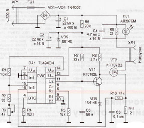
The stabilizer circuit is shown in fig. 1. The mains voltage rectifies the diode bridge VD1-VD4 and smoothes the capacitor C1. Thanks to a capacitor that increases the rectified voltage, the stabilizer maintains the average current through the heating element constant even when the mains voltage drops to 180 V. Power is supplied to the DA1 controller SHI chip from a parametric stabilizer R6, VD5 with smoothing capacitor C2. The current consumption of the DA1 chip is about 12 mA, so about 6 W is released on the quenching resistor R3,5, which is some disadvantage of the stabilizer. The controller includes a master sawtooth voltage generator, the frequency of which is determined by the elements R5, C3 and is equal to 0,9 kHz. It is calculated by the formula F=1,1 /(R5xC3) [2]. From the output C2 of the controller, control pulses with a period of 0,55 ms through an inverter made on the transistor VT1 are fed to the gate of a powerful regulating transistor VT2. The presence of an inverter reduces the likelihood of failure of the microcircuit during a breakdown of VT2. The source circuit VT2 includes a current sensor - resistor R11, rectangular pulses from which are fed to the integrating circuit R10C5. The amplitude of the pulses is about 0,3 V. From the output of this circuit, a constant voltage is supplied to the non-inverting input of the controller error signal amplifier (pin 16). An exemplary voltage Uref (pin 15) is applied to its inverting input (pin 14) through a resistive divider R1-R3. When the current through the load at the controller output C2 changes, the duty cycle of the pulses will change, maintaining the same voltage value at the inputs of the error signal amplifier. The average current through the soldering iron heating element will be kept constant. The variable resistor R3 regulates the heating temperature. LED HL1 - current indicator. The more current through the load, the brighter it shines.
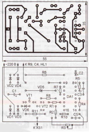
A drawing of a printed circuit board made of one-sided foil fiberglass is shown in fig. 2. All elements are mounted on it, except for HL1, C4, R3 and R9.
Structurally, the stabilizer is placed in an aluminum case of suitable dimensions painted on the outside. His photo is shown in Fig. 3. Transistor VT1 - any low-power structure npn, for example, the KT503, KT315 or VS 107 series. The KP707V2 transistor is installed without a heat sink, it can be replaced with an imported BUZ90. LED HL1 - low-power red glow of any type. Variable resistor R3 - PP2-12 (they are characterized by high reliability); R6 - ceramic SQP-5W, for better heat dissipation, pressed against the aluminum case through thermal paste. The rest of the resistors are any, for example MLT. Oxide capacitors - imported; WITH3, C5 - ceramic, for example, KM, K10-17. A properly assembled stabilizer starts working immediately. With the load connected, turning the knob of the resistor R3, observe the change in the brightness of the LED NI. Otherwise, check the voltage +12 V at pin 12 and +5 V at pin 14 of the controller. In this case, precautions should be taken, since the stabilizer is connected to a 220 V network. In the presence of an oscilloscope, pulses are monitored based on the transistor VT1, gate and source VT2. The source voltage (resistor R11) can be monitored with a conventional DC voltmeter. Literature
Author: S. Dobrovanov
Artificial leather for touch emulation
15.04.2024 Petgugu Global cat litter
15.04.2024 The attractiveness of caring men
14.04.2024
▪ Data transfer speed record over LiFi ▪ The computer mouse changes the way we see the world around us ▪ New Debug Platform for DaVinci Processors ▪ Development of technology for capturing greenhouse gases
▪ section of the site Fundamentals of safe life (OBZhD). Article selection ▪ article Tranquility of the cemetery. Popular expression ▪ article When Did Bhutanese Know You Can Smoke Marijuana? Detailed answer ▪ article Assembler of plastic products. Job description ▪ article Emergency power source. Encyclopedia of radio electronics and electrical engineering
Home page | Library | Articles | Website map | Site Reviews
www.diagram.com.ua |


 Leave your comment on this article: