Power supply of radio equipment from the on-board network of the car

Encyclopedia of radio electronics and electrical engineering /
Automobile. Electronic devices
 Comments on the article
Many people have portable receivers and tape recorders, and if you also have a car, then on the road it is more convenient to power these devices from the car battery without draining the batteries. It is impossible to connect radio equipment directly to the battery (with the exception of those devices that are intended for this), since its voltage can vary from 10 to 15 V, and portable equipment is powered by a lower voltage.
A feature of the car's on-board network with the engine running is the presence of impulse noise in the form of surges of positive and negative polarity, the amplitude of which can reach 160 V (decreasing after 1 ms). Pulses of positive polarity with an amplitude of up to 90 V also appear in the power circuit and fall off after 0,4 s.

Rice. 4.15. Scheme of the power supply of radio equipment from the mains of the car
The power supply unit (Fig. 4.15) eliminates all these overloads and provides a stabilized voltage of 9 V at the output (the load current can be up to 0,8 A). At the input of the power supply there are protective diodes VD1 and VD2, as well as a filter from the inductor L1 and capacitors C1 ... CXNUMX, which significantly attenuates interference.
If you are sure that you will not need to turn on the power of the radio equipment while the car is moving, then the L1 coil can be omitted.
To stabilize the output voltage, a widely used microcircuit KR142EN8A, G or 142EN8A, G is used, which is attached to a heat-dissipating plate.
The device has an internal overcurrent protection that is activated when it exceeds 1A.
For the manufacture of the filter coil, it is necessary to take ferrite armor cups of size B22 (Fig. 4.16) from ferrite grade 2000NM1 (1500NM1) and wind the turns on the internal dielectric frame with a PEL wire with a diameter of 0,25 mm until it is completely filled. Between the cups, you need to make a gap of about 0,1 ... 0,2 mm (inside), which will exclude the magnetization of the magnetic circuit by the constantly flowing current in the coil.

Rice. 4.16. Filter coil design
The circuit uses capacitors C1 of type K73-9, C2 ... C4 of type K50-35. As fuse F1, you can use a jumper made of wire with a diameter of 0,04 ... 0,07 mm.
The power supply can be connected to the on-board network through the cigarette lighter socket or an installed special connector.
The overall dimensions of the device do not exceed 70x60x40 mm (Fig. 4.17).
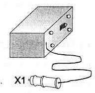
Ris.4.17
Publication: cxem.net
See other articles Section
Automobile. Electronic devices
 Read and write useful comments on this article.
<< Back
 Latest news of science and technology, new electronics:
Artificial leather for touch emulation
15.04.2024
In a modern technology world where distance is becoming increasingly commonplace, maintaining connection and a sense of closeness is important. Recent developments in artificial skin by German scientists from Saarland University represent a new era in virtual interactions. German researchers from Saarland University have developed ultra-thin films that can transmit the sensation of touch over a distance. This cutting-edge technology provides new opportunities for virtual communication, especially for those who find themselves far from their loved ones. The ultra-thin films developed by the researchers, just 50 micrometers thick, can be integrated into textiles and worn like a second skin. These films act as sensors that recognize tactile signals from mom or dad, and as actuators that transmit these movements to the baby. Parents' touch to the fabric activates sensors that react to pressure and deform the ultra-thin film. This ... >>
Petgugu Global cat litter
15.04.2024
Taking care of pets can often be a challenge, especially when it comes to keeping your home clean. A new interesting solution from the Petgugu Global startup has been presented, which will make life easier for cat owners and help them keep their home perfectly clean and tidy. Startup Petgugu Global has unveiled a unique cat toilet that can automatically flush feces, keeping your home clean and fresh. This innovative device is equipped with various smart sensors that monitor your pet's toilet activity and activate to automatically clean after use. The device connects to the sewer system and ensures efficient waste removal without the need for intervention from the owner. Additionally, the toilet has a large flushable storage capacity, making it ideal for multi-cat households. The Petgugu cat litter bowl is designed for use with water-soluble litters and offers a range of additional ... >>
The attractiveness of caring men
14.04.2024
The stereotype that women prefer "bad boys" has long been widespread. However, recent research conducted by British scientists from Monash University offers a new perspective on this issue. They looked at how women responded to men's emotional responsibility and willingness to help others. The study's findings could change our understanding of what makes men attractive to women. A study conducted by scientists from Monash University leads to new findings about men's attractiveness to women. In the experiment, women were shown photographs of men with brief stories about their behavior in various situations, including their reaction to an encounter with a homeless person. Some of the men ignored the homeless man, while others helped him, such as buying him food. A study found that men who showed empathy and kindness were more attractive to women compared to men who showed empathy and kindness. ... >>
|
Random news from the Archive
Canadian lakes are disappearing
25.07.2012
There are 1,3 million lakes in Canada. Many of them, especially small ones, do not even have a name - only a number. Satellite observations since 2000 have shown that many Canadian lakes are shrinking for some unknown reason. During 2000-2009, the country lost 6700 square kilometers of the total surface of lakes, that is, 1,2 percent of the water surface.
A possible explanation is the effects of global warming. Lakes in the north of the country may be shrinking due to the thawing of permafrost - the water simply goes into the thawed soil. In the south, increased evaporation can affect. Due to warming, winters have become less snowy and water bodies are less replenished in spring. But these hypotheses need to be tested.
|
News feed of science and technology, new electronics
 We recommend downloading in our Free technical library:
▪ site section Winged words, phraseological units
▪ Servo magazines (annual archives)
▪ book operation of diesel power plants. Stern V.I., 1980
▪ article When was a solar eclipse first predicted? Detailed answer
▪ article by Eugene. Legends, cultivation, methods of application
▪ article Coin and handkerchief. Focus Secret
▪ reference book Service menus of foreign TVs. Book #2
Leave your comment on this article:
 All languages of this page
Home page | Library | Articles | Website map | Site Reviews

www.diagram.com.ua
2000-2024


 Arabic
 Bengali
 Chinese
 English
 French
 German
 Hebrew
 Hindi
Hindi Italian
 Japanese
 Korean
 Malay
Malay Polish
 Portuguese
 Spanish
 Turkish
 Ukrainian
 Vietnamese