|
|


 Arabic
 Bengali
 Chinese
 English
 French
 German
 Hebrew
 Hindi
Hindi Italian
 Japanese
 Korean
 Malay
Malay Polish
 Portuguese
 Spanish
 Turkish
 Ukrainian
 Vietnamese
|
ENCYCLOPEDIA OF RADIO ELECTRONICS AND ELECTRICAL ENGINEERING Desoldering iron with solder suction. Encyclopedia of radio electronics and electrical engineering
Encyclopedia of radio electronics and electrical engineering / Ham Radio Technologies The proposed device is convenient for repairing equipment and disassembling old printed circuit boards. Its efficiency is so high that it allows you to solder a forty-pin microcircuit from a two-sided board in about a minute. The soldering iron works with an external vacuum pump, for which I use a compressor from a household refrigerator with minor alterations, but a regular vacuum cleaner is also suitable. The desoldering iron differs from the usual one in the design of the heating head. Its device is shown in Fig. 1. A ceramic tube 1 with a diameter of 45 ... 2 mm is put on a brass tubular soldering rod 2 with a length of 6 and a diameter of 7 mm from a fuse. Winding 3 of the heater is wound around the ceramic tube, consisting of 5 ... 7 turns of nichrome wire with a diameter of 0,4 ... 0,5 mm. One of the winding leads is connected to the soldering rod and the body of the soldering iron, the second is made with copper wire 11 in heat-resistant insulation. Heat insulator 4 is superimposed on the heater from the outside in the form of two layers of sheet mica and a winding of corded asbestos.
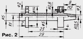
The soldering rod is fixed in a thin-walled steel tube 5 with a diameter of 3 mm, which serves as a drain channel for the absorbed solder; tube length 75 mm. The protective cover 6 is bent from sheet steel with a thickness of 0,5 ... 0,8 mm and is tightly inserted into the hole of the handle 7, made of wood, heat-resistant plastic or papier-mâché. At the end of the tube 5 is put on a length of 30...40 cm rubber elastic hose 8. The second end of the segment is connected to the solder storage. The design of the soldering iron is designed for manufacturing and assembly without the use of machine tools. One of the ends of the blank of the soldering rod 1 is formed by blows of a light hammer and a file is used to give the tip of the rod the final shape, like a conventional soldering iron. The diameter of the suction hole in the sting should not exceed 1 mm. When choosing a workpiece, it is necessary to make sure that its material is easily tinned. The rod can also be made of copper, but its durability will be less. A steel outlet tube 5 is tightly put on the rear end of the soldering rod. Then a ceramic tube 2 is put on the soldering rod. If it does not fit tightly, one or two layers of thin mica are wound on the rod under it. If a ready-made mica tube of a suitable diameter is at hand, it can be replaced with a ceramic one. The end of the nichrome wire is fixed on the soldering rod with a one-two-turn bandage and tightened tightly, providing good electrical contact. The heater winding is wound in increments of 0,8 ... 1 mm, the second end of the wire is fixed with the same bandage and pin 11 is attached. Near the left end of the outlet tube 5 in the figure, a bandage 9 of copper wire in cotton and vinyl insulation is tightly wound - this will be the second output of the heater winding. A rubber tube 8 is put on the end of the tube and fixed with a bandage and, having installed the gasket 10, the assembly is inserted into the casing 6. The gasket is a strip of sheet rubber, which is wrapped around the tube 5, laying the heater outlet end-to-end. The thickness of the gasket is selected so that the casing fits tightly into the hole of the handle 7, coaxially fixing the outlet tube. From the side of the heater, a metal clamping ring 12 is pushed onto the casing with force, the inner diameter of which is chosen in such a way that the edges of the casing converge closely. In this case, the thickness of the heat-insulating asbestos winding should be sufficient for tight fixation of the heater. In order to reduce heat transfer from the heater to the handle, several rows of staggered holes should be drilled in the casing - in its middle part. The solder accumulator is a glass cylindrical cup with a capacity of up to 200 cm3, tightly closed with a plastic lid. Three holes are drilled in it, short pieces of a thin-walled tube of approximately the same diameter as the outlet in the soldering iron are hermetically installed in two of them. Outwardly, both pipes should protrude by 15 ... 20 mm, and inside the inlet - by about half the depth of the glass, the outlet - by a third. It is necessary to put on and fix the simplest filter case made of rare fabric on the inner end of the outlet pipe so as not to damage the vacuum pump by accidental hit of solder balls. The free end of the rubber hose of the soldering iron is put on the outer end of the inlet pipe; the outlet pipe is connected to the inlet of the vacuum pump. It is necessary to power the soldering iron from a step-down transformer with a power of about 40 watts. To calculate the transformer, it is necessary to determine the optimal values of the voltage and current of the heater using LATR (approximately 7 ... 10 V and 3 ... 4 A). Although it is convenient to operate a soldering iron in tandem with LATR, it is very dangerous - it can cause an electric shock! In addition, soldered CMOS chips can be damaged. Therefore, it is necessary to use a step-down transformer and the soldering iron tip must be grounded. After heating the soldering iron, turn on the vacuum pump and, heating the place of soldering until the solder melts, close the free hole in the storage cover with your finger for a short time. All the solder will be instantly sucked into the tip hole. The disadvantages of the soldering iron of the described design include the fact that after prolonged use of it, the air channel is clogged with solder and requires cleaning. If it is possible to use a lathe, then the design of the heater can be improved. A drawing of a turned soldering rod is shown in fig. 2.
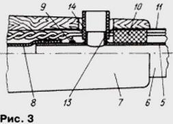
Several layers of sheet mica are wound between the cheeks (strip width 20 mm). The initial output of the heater winding is inserted into a hole with a diameter of 0,8 mm in the right cheek according to the drawing and fixed with an M2 screw. In addition to the hole for the locking screw, two more of the same holes with an M2 thread (not shown in Fig. 2) were drilled in the right cheek for attaching the casing. The final output is passed into a hole with a diameter of 2 mm in the left cheek, into which a piece of ceramic tube from the CPC condenser is tightly inserted (the outer lining is ground off with a needle file). The winding is covered from the outside with a heat insulator. A branch tube is pressed onto the shank of the soldering rod, which is left in the figure. On a lathe, it is easy to make a seat diameter for a tube of different diameters. The design of the handle in this version of the soldering iron has also been improved (Fig. 3).
A side hole is drilled in the outlet tube 5 and a short pipe 13 is soldered into it, on which, after assembling the soldering iron, a piece 14 of a plastic tube is put on. This hole must be closed with a finger to suck the solder. The third hole in the cover of the drive in this case, of course, is not needed. Such a scheme of the air channel made it possible to reduce the clogging with solder. Author: V.Rotar, Magadan
Artificial leather for touch emulation
15.04.2024 Petgugu Global cat litter
15.04.2024 The attractiveness of caring men
14.04.2024
▪ Infineon TLT807 - 24V Automotive Bus Linear Regulator ▪ Inkjet printers print finished electronic devices ▪ Microchip LoRa RN2483 IoT Wireless Module ▪ Samsung steps up its work in the digital camera market ▪ Radeon RX 6600 XT graphics accelerator
▪ section of the site Electronic directories. Article selection ▪ article An offer you can't refuse. Popular expression ▪ article Who managed to visit both a dwarf and a giant in his life? Detailed answer ▪ article Midwife examination room. Job description ▪ Clay's article. Encyclopedia of radio electronics and electrical engineering ▪ article Propagation of radio waves. Encyclopedia of radio electronics and electrical engineering
Home page | Library | Articles | Website map | Site Reviews
www.diagram.com.ua |


 Leave your comment on this article: