|
|


 Arabic
 Bengali
 Chinese
 English
 French
 German
 Hebrew
 Hindi
Hindi Italian
 Japanese
 Korean
 Malay
Malay Polish
 Portuguese
 Spanish
 Turkish
 Ukrainian
 Vietnamese
|
ENCYCLOPEDIA OF RADIO ELECTRONICS AND ELECTRICAL ENGINEERING Voltage controlled load power regulator. Encyclopedia of radio electronics and electrical engineering
Encyclopedia of radio electronics and electrical engineering / Power regulators, thermometers, heat stabilizers The author of the proposed article has repeatedly used the KR1182PM1A phase power controller chip in various designs [1] and made sure that it behaves excellently if the adjustment is made by changing the active resistance in the control circuit. However, when it was necessary to use the constant voltage supplied to the corresponding inputs of the microcircuit as a control action, problems arose. It was necessary, abandoning the KR1182PM1A microcircuit, to develop instead a relatively simple phase regulator, controlled by voltage and satisfying all the requirements for it.
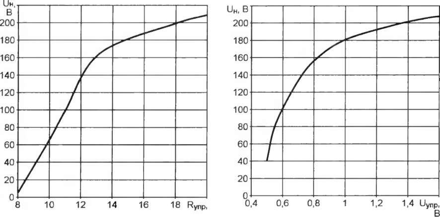
The experimentally measured dependence of the effective value of the voltage U on the active load of the KR1182PM1A microcircuit on the resistance of the resistor Rynp connected between its terminals 6 and 3, at a supply voltage of 220 V, is shown in Fig. 1. It indicates that the interval of change of this resistance from full shutdown to full turn on of the load is quite large. By setting a variable resistor with a nominal value of 22 kOhm as a regulating resistor, you can manually smoothly change the power. However, in automatic or remote control systems, it is more convenient to regulate the power not by resistance, but by the voltage between the terminals of the KR1182PM1A microcircuit. Although its reference data [2] states that its maximum value is 6 V, the experiments performed do not confirm this. Shown in fig. 2, the experimental dependence of the voltage at the load UH on the voltage applied between pins 6 (plus) and 3 (minus) of the control voltage Uynp microcircuit shows that the interval of its change from complete shutdown to full load on is only slightly more than 1 V.
The experiments were carried out with a load with a nominal power of 75 W. The control voltage was supplied from an isolated source. A protective 6 V zener diode was connected between pins 3 and 5,1. However, after withstanding a certain number of on and off, the microcircuit eventually stopped working. After two KR1182PM1 microcircuits went to the basket, the experiments were stopped.
Of course, two burnt microcircuits still do not give grounds to draw final conclusions. But in amateur conditions, each of them is valuable, especially since the KR1182PM1 microcircuits cannot be classified as cheap. It was decided, abandoning them, to develop a more reliable device on discrete elements. It also turned out that the total cost of its parts differs little from the price of one KR1182PM1 chip. The scheme of the developed voltage-controlled phase regulator is shown in fig. 3. It is used to control aquarium lighting. The control voltage Uynp slowly rises and falls, simulating "dawn", "day", "sunset" and "night" for fish. Timing diagrams in fig. 4 explain the operation of the regulator. The voltage from the diode bridge (curve 1) pulsating with the doubled mains frequency is applied through the resistors R1-R3 to the radiating diode of the optocoupler U1. The zener diode VD2 is necessary to limit the amplitude of the current pulses flowing through this diode. During these pulses, the phototransistor of the optocoupler is open, and in the pauses between them (at moments close to zero crossings of the mains voltage) it is closed. The shape of the pulses on the collector of this transistor is shown by curve 2. In the intervals between them, a stable current generator operates on the transistor VT1. Capacitor C1 is charging, the voltage across it increases linearly (curve 3). During the pulse, the transistor VT2 opens and discharges the capacitor.
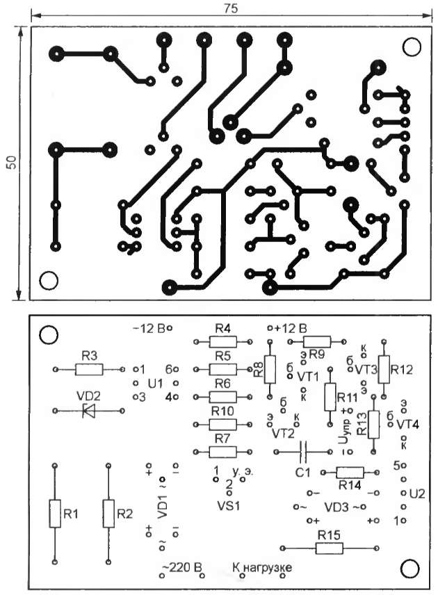
The voltage from the capacitor is supplied to the base of the transistor VT3, to the emitter of which the control voltage Iupr is applied. Its level is shown in curve 3 by a dashed line. While the voltage on the capacitor is less than the control voltage, the transistor VT3 is closed, when it is greater, it is open. Together with it, the transistor VT4 opens and closes, in the collector circuit of which the emitting diode of the optocoupler U2 is included. The pulses of the current flowing through it are curve 4. They are the shorter, the closer the control voltage is to the amplitude value of the voltage on the capacitor C1 and the later in each half-cycle of the mains voltage the photodistor of the optocoupler U2 and the triac VS2 open. The effective value of the voltage on the load is maximum at zero control voltage and decreases with its increase. The printed circuit board of the regulator is shown neither in fig. 5. It is powered by any 12 V DC source. The maximum control voltage is 3 ... 4 V less than the supply voltage. KT3102A transistors can be replaced by others of the same series, and KT3107K - by KT3107L transistors, in extreme cases KT3107D-KT3107I. The permissible load power depends on the triac used. The applied TC106-10 allows you to control a load with a power of up to 2 kW. With its power up to 100 W, it is not required to remove heat from the triac. Literature:
Author: G. Martynov, Donetsk, Ukraine; Publication: radioradar.net
Machine for thinning flowers in gardens
02.05.2024 Advanced Infrared Microscope
02.05.2024 Air trap for insects
01.05.2024
▪ Color vision weakens towards the periphery ▪ DVD recorders will replace VCRs
▪ website section LEDs. Article selection ▪ article There is no prophet in his own country. Popular expression ▪ article Why is yawning contagious? Detailed answer ▪ article Electrician of linear communication facilities. Standard instruction on labor protection ▪ article Power supply project. Encyclopedia of radio electronics and electrical engineering
Home page | Library | Articles | Website map | Site Reviews
www.diagram.com.ua |


 Leave your comment on this article: