|
|


 Arabic
 Bengali
 Chinese
 English
 French
 German
 Hebrew
 Hindi
Hindi Italian
 Japanese
 Korean
 Malay
Malay Polish
 Portuguese
 Spanish
 Turkish
 Ukrainian
 Vietnamese
|
ENCYCLOPEDIA OF RADIO ELECTRONICS AND ELECTRICAL ENGINEERING Linear transistor KB amplifier with a power of 50 watts. Encyclopedia of radio electronics and electrical engineering
Encyclopedia of radio electronics and electrical engineering / RF power amplifiers The IRF520 linear power amplifier based on field-effect transistors, developed by the Polish radio amateur Jerzy Mroszczak (SQ7JHM), differs from most of the technical solutions known nearby, although not new, but rather rarely used. Its good parameters and high signal quality are confirmed by a large number of positive feedback received from correspondents in QSOs conducted by the author.
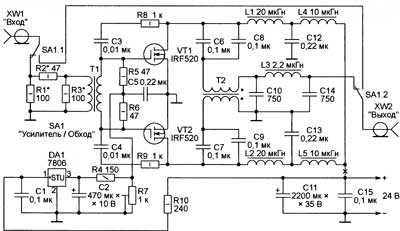
The appearance of the amplifier is shown in fig. 1, and its diagram is in Fig. 2. The amplified signal applied to the XW1 connector enters through an attenuator of resistors R1-R3 and a transformer T1 to the gates of field-effect transistors VT1 and VT2. The scheme used provides good symmetry of the gate signals. With the help of a tuning resistor R7, a constant bias is set on the gates of the transistors, which provides a quiescent current in the circuit of their drains (in the absence of an alternating voltage at the gates) of about 80 ... 100 mA. The total quiescent current, which can be measured by connecting the ammeter to the break in the power wire marked in the diagram with a cross, is twice as much - 160 ... 200 mA. At maximum output power, the current here increases to approximately 4 A.
The resistive attenuator serves to better match the amplifier with the signal source and dampen the excess power of this signal. The values of the resistors R1-R3 indicated in the diagram are optimal when working from the Kajman transceiver used by the QRP author with an output power of 2 watts. In other cases, these resistors may have to be re-selected. Transformer T1 is wound with double-folded insulated copper wire with a diameter of 0,55 mm on a ring ferrite magnetic circuit FT-82-43. Its windings contain 11 turns. The amplifier uses an original unit for summing the output signals of the arms of a push-pull amplifier, assembled on a T2 transformer, which also serves to match the amplifier with a 50-ohm load. Isolating capacitors C6-C9 do not allow the DC component of the transistor drain current to pass into the transformer windings. This saves its magnetic circuit from unwanted bias, which may result in increased non-linear distortion of the output signal, insufficient power, and an increased level of harmonics at the output. The design and number of turns of the windings of the transformer T2 are the same as those of T1. But its magnetic circuit is glued from two ferrite rings FT-114-43, and the diameter of the winding wire is 1 mm. It is impossible to get rid of the DC component of the current flowing in the windings of the inductors L1, L2, L4, L5. The danger of saturation is eliminated here in a different way - by using open rod rather than closed ring magnetic circuits. Chokes L1 and L2 have 25 turns of wire 1 mm in diameter, wound on a ferrite rod with a diameter of 8 mm, and chokes L4 and L5 - 20 turns of the same wire on a rod 5 mm in diameter. The author, unfortunately, does not report the magnetic permeability of ferrite rods, saying only that it should be high. Coil L3 is wound on an annular magnetic circuit T68-2 made of carbonyl iron. It contains 19 turns of wire with a diameter of 0,9 mm. The printed circuit board of the amplifier is shown in fig. 3. The foil on its reverse side is completely preserved. With several wire jumpers passed through specially drilled holes, it is connected to a common printed conductor on the front side. Windows are made for the cases of field-effect transistors in the board, and the transistors themselves are mounted on heat sinks. Transistors must be selected with a parameter spread of no more than 10%. If this fails, shown in Fig. 3 wire jumpers in the source circuits of the transistors must be replaced with resistors with a resistance of 0,22 ohms and a power of 2 watts.
When a sinusoidal signal with an amplitude of 9 V was applied to the input of the amplifier, a power of 50 W was obtained at its load of 55 Ohms. According to the author, it depends little on the frequency in the entire KB range, which, unfortunately, he does not indicate the boundaries of and the magnitude of the unevenness. Publication: radioradar.net
Artificial leather for touch emulation
15.04.2024 Petgugu Global cat litter
15.04.2024 The attractiveness of caring men
14.04.2024
▪ Magic Leap 1 Mixed Reality Headset ▪ Sony Handycam FDR-AX4E 1K camcorder ▪ Processing moon dust into oxygen ▪ The latest solar panels for spacecraft
▪ section of the Radio Control website. Article selection ▪ Molotov cocktail article. Popular expression ▪ article How did lunar craters form? Detailed answer ▪ article LED rechargeable flashlight. Encyclopedia of radio electronics and electrical engineering
Home page | Library | Articles | Website map | Site Reviews
www.diagram.com.ua |


 Leave your comment on this article: