|
|


 Arabic
 Bengali
 Chinese
 English
 French
 German
 Hebrew
 Hindi
Hindi Italian
 Japanese
 Korean
 Malay
Malay Polish
 Portuguese
 Spanish
 Turkish
 Ukrainian
 Vietnamese
|
ENCYCLOPEDIA OF RADIO ELECTRONICS AND ELECTRICAL ENGINEERING High temperature indicator on the KIA6966S chip. Encyclopedia of radio electronics and electrical engineering
Encyclopedia of radio electronics and electrical engineering / Power regulators, thermometers, heat stabilizers The diagram of a five-threshold indicator-signaling device with an external temperature sensor (thermistor) is shown in fig. one. The KIA6966S (DA1) chip used in it usually controls a line of five LEDs in devices for visual monitoring of the level of audio signals in tape recorders and UMZCH. In this case, a constant voltage is supplied to the input (pin 8) of the DA1 chip, depending on the temperature of the controlled object. The miniature thermistor RK1 has a negative temperature coefficient of resistance (the higher the temperature, the lower it is). Therefore, as the temperature increases, the voltage between the terminals of the thermistor decreases, therefore, the voltage at the DA1 input decreases relative to the common wire. The lower this voltage, the greater the number of LEDs HL2-HL6, starting from HL2, will be turned on.
Unfortunately, the scale turns out to be non-linear. In the KIA6966S chip, it is deliberately made logarithmic, which is necessary for using the chip for its intended purpose. This adds to the non-linearity of the temperature characteristic of the thermistor. Therefore, the temperature values indicated for the LEDs in the diagram are only considered indicative. If necessary, they can be refined by placing the thermistor in an environment with a temperature controlled by a reference thermometer. When, signaling the excess of the maximum allowable temperature. the HL6 LED turns on, the transistor VT2 also opens at the same time. Through it, the supply voltage is supplied to the generator 34, assembled on transistors VT1 and VT3. The generator starts to work, and the device with the help of an electromagnetic emitter HA1 gives a sound signal. A stabilized voltage of 5 V for powering the indicator nodes was obtained from the integral stabilizer DA2. A constant voltage of 7 ... 15 V from any source and even an alternating voltage of 6 ... 12 V can be applied to its input. The indicator consumes a current of about 6 mA when the LEDs are off HL2-HL6 and 56 mA when they are all on and the buzzer is working. The Schottky diode VD1 protects against reversed polarity of the DC supply voltage or serves as a half-wave AC rectifier. The C1L1C4 filter eliminates the mutual influence of the indicator and the device that serves as a source of supply voltage. The HL1 LED indicates the presence of power and serves as the "starting point" of the LED scale.
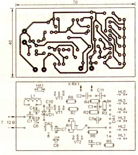
The device can be mounted on the printed circuit board shown in fig. 2 It has one jumper wire Trimmer resistor R1 must be of high quality and reliability. The author used an imported small-sized one in a dustproof case. From domestic ones, we can recommend multi-turn SP5-14, SP5-2, SPZ-39, single-turn SP5-16. The oxide capacitor C6 is “laid” on the board to reduce the mounting height. The highest elements on it are the LEDs, for which holes are drilled in the cover of the signaling device. Schottky diode 1N5819 can be replaced with similar 1N5817, 1N5818, MBR0530T1. Ordinary diodes 1 N4001, KD243A are also suitable. Instead of the RN2907A and 2SA733P transistors, you can install any of the KT3107, KT686 series, and instead of 2SC945P - the KT3102 series. LEDs are suitable for any general application of continuous light. As HL6, to increase the visibility of the signal, you can use a blinking LED, for example, L-36BSRD B But in series with it, you should turn on a conventional diode (for example, 1N914) with a cathode to pin 6 of DA1 and resistor R6. The sound emitter DBX-12PN can be replaced by another small-sized electromagnetic one with a winding resistance of at least 40 ohms. The assembled indicator needs to be adjusted. First of all, it is necessary to connect the outputs of the emitter and collector of the transistor VT2 with a jumper and, by selecting the resistor R7, to achieve stable excitation of the sound generator when the power is turned on. After that, the jumper must be removed. Place the thermistor RK1 in 1 waterproof plastic bag, lower it into water at a temperature of 80 C (control by a reference thermometer) and adjust the variable resistor R1 to turn on all the LEDs and the sound signal. As the water cools, the LEDs should alternately turn off. HL45 goes out last at 2°C. If the temperature of its shutdown differs from the desired one, the resistor R4 is selected. After that, the water temperature is again brought to 80 ° C and the above operations are repeated until the desired result is achieved. To control the temperature of a heated object, the thermistor RK1 is fixed on its surface in any way possible. For better thermal contact, you can fill the remaining air gap with thermally conductive paste. If the monitored surface is energized, an insulating gasket can be placed between it and the thermistor. When choosing it, keep in mind that the amplitude of the pulses, for example, on the collector or drain of a powerful transistor in a switching power supply, can reach 1000 V. The presence of a thick gasket or a large gap increases, of course, the error in determining the temperature and slows down the response of the device to its unexpected increase . When changing the sensor, such a device can also be used for the operational control of other physical quantities, including illumination, humidity or air pressure. Author: A.Butov, village of Kurba, Yaroslavl region; Publication: radioradar.net
Machine for thinning flowers in gardens
02.05.2024 Advanced Infrared Microscope
02.05.2024 Air trap for insects
01.05.2024
▪ Accelerator GeForce GTX 970 EXOC Sniper Edition ▪ Thin plasma emitters: a revolution in noise reduction
▪ site section Low frequency amplifiers. Article selection ▪ article Like the sun in a small drop of water. Popular expression ▪ article How did the fire appear? Detailed answer ▪ headhunter article. Job description ▪ article Manage loads from COM or USB. Encyclopedia of radio electronics and electrical engineering
Home page | Library | Articles | Website map | Site Reviews
www.diagram.com.ua |


 Leave your comment on this article: