|
|


 Arabic
 Bengali
 Chinese
 English
 French
 German
 Hebrew
 Hindi
Hindi Italian
 Japanese
 Korean
 Malay
Malay Polish
 Portuguese
 Spanish
 Turkish
 Ukrainian
 Vietnamese
|
ENCYCLOPEDIA OF RADIO ELECTRONICS AND ELECTRICAL ENGINEERING Medium wave receiver with synchronous detector. Encyclopedia of radio electronics and electrical engineering
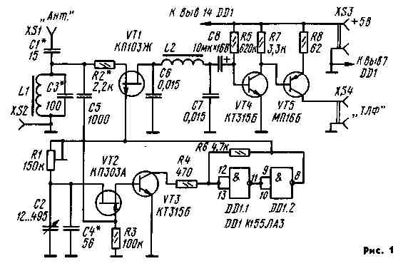
Encyclopedia of radio electronics and electrical engineering / radio reception When developing the described receiver, the author set himself the task of creating a simple design suitable for repetition by radio amateurs taking the first steps in mastering synchronous radio reception. Synchronous receivers are known to have high selectivity and provide linear detection of AM signals, which explains the growing interest in them. The very name of the receiver indicates that reception on it is possible when the local oscillator voltage is synchronized with the signal voltage, i.e., the local oscillator frequency is equal to the signal frequency. The local oscillator is synchronized, as a rule, by the method of phase locked loop (PLL) or by the method of direct capture of the local oscillator frequency by the input signal. In this case, the second, as the simplest, synchronization method is used. Let us turn to the consideration of the circuit diagram of the receiver shown in Fig. 1. A broadband oscillatory circuit L1C3 is installed at the input, tuned to the middle of the selected section of the CB range by selecting capacitor C3. Such a change can be realized with a set of capacitors switched discretely by means of a switch. The mixer is made on the transistor VT1, the input signal to which is fed through the resistor R2, which plays the role of an attenuator.
The attenuator is designed to reduce crosstalk that occurs during direct detection of strong signals due to the non-linearity of the FET channel. The attenuator resistance is selected based on the specific reception conditions. The local oscillator voltage is supplied directly to the gate of the transistor VT1, operating in the key mode, the functions of the local oscillator are performed by a controlled RC oscillator, which is based on a Schmitt trigger on a digital microcircuit DD1. The trigger generation mode is provided by including a controlled frequency-dependent RC circuit in its positive feedback circuit. The local oscillator frequency is determined by the elements R1, C2, C4 and the channel resistance of the transistor VT2, to the gate of which a synchronizing input signal is supplied through the capacitor CS. With the values of the elements indicated in the diagram, the tuning range of the local oscillator is approximately 300 kHz. The middle frequency of the range is set by the tuning resistor R1. Smooth tuning of the local oscillator frequency over the range is carried out by a capacitor of variable capacitance C2. When the local oscillator frequency is close to the carrier frequency of the input signal, it is captured and the frequencies of the local oscillator and the input signal are equal. In this case, the mixer provides synchronous detection of the input signal. The audio signal after the mixer is separated by an L2C6C7 filter with a cutoff frequency of 5 kHz. The receiver's AF amplifier is made on transistors VT4, VT5, connected according to a direct-coupled circuit. The mode of operation of both transistors is set by resistors R5 and R7. The last stage of the AF amplifier is loaded onto low-resistance telephones TA-56M with a DC resistance of 50 ohms. Resistor R8 limits the amount of current drawn by the last stage of the AF amplifier and provides negative AC feedback, which increases the linearity of the gain. A stabilized source is desirable to power the receiver, but a fresh 3336L battery or a battery composed of several cells that provide the required supply voltage can also be used. The current drawn by the receiver is approximately 30 mA. Its performance is maintained when the supply voltage is reduced to 4 V. The receiver is mounted on printed circuit board from double-sided foil fiberglass, placed in a case soldered from the same fiberglass, or in any other suitable metal box. The dimensions of the case are chosen arbitrarily, they are limited only by the dimensions of the board and the variable capacitor. On the side walls of the case, sockets are installed for connecting the power source, headphones, antenna and ground. All transistors, except for the output, can be with any letter index. Ceramic capacitors are used in the high-frequency part of the receiver. A variable capacitor can be taken from a portable receiver. Capacitors C6, C7 and C8 can be of any type. Resistors - MLT-0,25 or MLT-0,125, tuning resistor R1 - SDR - 16. Coil L1 is wound with PEL 0,2 wire on a K7x4x2 ring made of 600NN ferrite and contains 30 turns. In this case, the tuning frequency of the input circuit, with the value of the capacitor C3 indicated in the diagram, is 1250 kHz. Coil L2 is wound on a K18x9x5 ring made of 2000 NN ferrite and contains 260 turns of PEL 0,2 wire. Setting up the receiver begins with checking the AF amplifier. When you touch its input with a screwdriver, a strong low-frequency alternating current background should be heard in the phones, indicating the normal operation of the amplifier. It does not require additional settings when using serviceable parts. You can check the presence of generation and set the tuning range of the local oscillator by listening to its signal on a nearby medium-wave broadcasting receiver. The tuning range of the local oscillator is determined by the main (lowest) frequency of its radiation. By changing the resistance of the resistor R1, the average frequency of the local oscillator is shifted so that the area of interest in the CB range falls into it. After that, by selecting the capacitor C3, the input circuit is tuned to the average frequency of the selected section of the range. Its setting is controlled using a standard signal generator (GSS) and a high-frequency millivoltmeter or oscilloscope. The signal from the GSS through a resistor with a resistance of 100 kOhm is fed to the circuit and its resonant frequency is determined by the maximum voltage on it. It should be noted that the bandwidth of the circuit already included in the receiver is significantly expanded due to the shunting action of the attenuator and mixer. This makes it possible to receive signals from several stations that are closely spaced in frequency without changing the input circuit. Despite its simplicity, the tuned receiver has a high sensitivity, allowing you to receive signals from very remote radio stations on an antenna in the form of a piece of wire 1 m long and connected to ground. The disadvantage of the receiver is the low frequency stability of its local oscillator, which is characteristic of all RC generators. Therefore, in the process of receiving, especially weak signals, due to the influence of destabilizing factors, synchronization may be disturbed and it will be necessary to adjust the receiver. Author: A. Rudnev, Balashov, Saratov region; Publication: N. Bolshakov, rf.atnn.ru
Artificial leather for touch emulation
15.04.2024 Petgugu Global cat litter
15.04.2024 The attractiveness of caring men
14.04.2024
▪ The ability to concentrate is more important than the amount of memory ▪ Cap of invisibility from ordinary lenses ▪ Boat jet engine on outboard water
▪ section of the website job descriptions. Article selection ▪ article Lamarck Jean-Baptiste. Biography of a scientist ▪ article How did the sandwich come about? Detailed answer ▪ Kinkan article. Legends, cultivation, methods of application ▪ article The spectator knows the secret of the trick, but cannot repeat it. Focus Secret
Home page | Library | Articles | Website map | Site Reviews
www.diagram.com.ua |

 Leave your comment on this article: