|
|


 Arabic
 Bengali
 Chinese
 English
 French
 German
 Hebrew
 Hindi
Hindi Italian
 Japanese
 Korean
 Malay
Malay Polish
 Portuguese
 Spanish
 Turkish
 Ukrainian
 Vietnamese
|
ENCYCLOPEDIA OF RADIO ELECTRONICS AND ELECTRICAL ENGINEERING SSB transceiver for 80 meters. Encyclopedia of radio electronics and electrical engineering
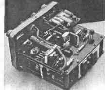
Encyclopedia of radio electronics and electrical engineering / Civil radio communications The transistorized 80m transceiver has been in operation since June 1974. Many connections were made on it, and the correspondents invariably assessed the quality of the signal as good. Transceiver transmitter power - about 0,5 W, receiver sensitivity with a signal-to-noise ratio of 10 dB - not worse than 1 μV. The appearance of the transceiver is shown in fig. one.
The schematic diagram of the transceiver is shown in fig. 2. It is assembled on 22 transistors. In the transmission mode, the voltage developed by the microphone is fed to the bass amplifier, made on transistors T2 and T3. Amplified voltage is supplied through capacitor C61 to the inputs of the voice control device - VOX (transistors T20-T22) and ring balanced modulator (diodes D1-D4). A voltage with a frequency of 500 kHz of the reference crystal oscillator (T9, T10) is also supplied to the balanced modulator. From the output of the balanced modulator, the signal is fed to the F1 EMF, which selects the upper side band, forming an SSB signal. This signal is mixed in a mixer on transistors T4-T5 with a signal with a frequency of 4,1-4,15 MHz of a smooth range generator (GPA). GPA is made on the transistor T11. Cascades on transistors T12, T13 and T14 serve to reduce the destabilizing effect of the load. A cascode amplifier (T6, T7) is switched on after the mixer. Its load is the L4C13 circuit, tuned to a frequency of 3,625 MHz. As a result of mixing in this circuit, an operating frequency signal is allocated, which has a lower sideband. It is fed to the output stage on the transistor T8. This cascade works in light mode. To tune the transmitter, a sound generator is provided on the transistor T], connected to the input of the bass amplifier with the Kn1 button. In the receive mode, the voltage from the antenna is fed to the input of an RF amplifier made on a TI5 transistor. The amplified voltage is applied to the base of the transistor T16 of the receiver mixer. The emitter of the transistor is energized by the GPA. The load of the mixer is the FSS, which extracts the intermediate frequency signal (500 kHz). After the FSS, the intermediate frequency voltage is amplified by a single-stage IF amplifier (T17) and then fed to the ring mixing diode detector (D11-D14). The voltage of the reference crystal oscillator is also supplied here. A low-frequency voltage is emitted at the output of the detector, which is then amplified by a two-stage low-frequency amplifier made on T18 transistors. T19. The load of the bass amplifier is high-impedance headphones. The receiver gain is separately adjusted for LF and IF by resistors R45 and R39, respectively. To detun the receiver within a small range, a D6 varicap is used. The detuning frequency is changed by adjusting the bias voltage on the varicap resistor R52. The detuning is used only in the receive mode, but it can also be used in the transmit mode by changing the switching scheme accordingly. The transition of the transceiver from reception to transmission is carried out by contacts P1 / 1 of relay P1 of the voice control device. Construction and details The transceiver is assembled on two main printed circuit boards. The first one contains the SSB signal generator and VOX, the second one contains the receiving part and the GPA, and the cascades on transistors T11 and T12 are assembled on a separate small board and placed on the screen. The mixer, buffer amplifier and final stage are also assembled on a separate board and placed in a shield attached to the second main board. A sound generator is made on the third separate board. The main printed circuit boards are located in two floors. The design used small parts: fixed resistors - ULM; capacitors GPD-KSO, C 15, C24, C37-with an air dielectric; transformers Tr1, Tr2 and coils FSS L14-L18 - from the Alpinist radio receiver (transformers - transitional matching). The data of the remaining coils and inductor Dr1 are indicated in the table. Coils L1, L2, L3 and the choke are wound in bulk, the rest are coil to coil. Coil frames L4, L5 and L12, L13 are equipped with SCR-1 carbonyl iron cores. Relay P1 - any type with a trip current of 20 mA, for example, RES-10 (RS4.524.301).
Setting As usual, it begins with checking the installation and performance of each cascade. First, the operability of the LF amplifiers, GPA, and the quartz oscillator is checked. After making sure that these cascades are working, the GPA frequency range is set in the range from 4,1 to 4,15 MHz using a wavemeter or a reference receiver. By applying a voltage from the GSS to the input of the receiving part of the transceiver with a frequency of 3,625 MHz and an amplitude of about 0,1 mV, the L17C55 circuit, the FSS and the C10C37 circuit are sequentially tuned to the maximum output signal. The transmitting part of the transceiver is adjusted using the signal of the sound generator (with the Kn1 button pressed). The adjustment comes down to balancing the balanced modulator with resistor R11 and tuning the L4C13 and L6C15 circuits to a frequency of 3,625 MHz. When establishing the transmitting part, the equivalent of the antenna should be connected to the output of the transistor - a resistor with a resistance of 75 ohms and a power of 1-2 watts. Author: V. Tabunshchikov, village of Borovka, Vitebsk region; Publication: N. Bolshakov, rf.atnn.ru
A New Way to Control and Manipulate Optical Signals
05.05.2024 Primium Seneca keyboard
05.05.2024 The world's tallest astronomical observatory opened
04.05.2024
▪ Solar and wind energy for the entire US state ▪ It will be impossible to control superintelligent AI ▪ Creating the Perfect Chocolate Texture
▪ section of the site Car. Article selection ▪ article Russia, washed with blood. Popular expression ▪ article Which insect has a mechanism for converting solar energy into electricity? Detailed answer ▪ article Copier operator. Standard instruction on labor protection ▪ article Guessing the cards laid out in the absence of a magician. Focus Secret
Home page | Library | Articles | Website map | Site Reviews
www.diagram.com.ua |

 Leave your comment on this article: