
|
|
ENCYCLOPEDIA OF RADIO ELECTRONICS AND ELECTRICAL ENGINEERING Calculation and design of acoustic systems. Encyclopedia of radio electronics and electrical engineering
Encyclopedia of radio electronics and electrical engineering / Speakers Case without back wall The main resonance frequency of such a case
where I is the depth of the box, m; S - hole area, m2. An increase in acoustic power at the fundamental resonance frequency by 3-6 dB with relatively flat and 6-10 dB with deep cases gives the studied sound an unnatural timbre. If fH = fG, then the increase in acoustic power at lower frequencies is most significant. It is advisable to use a loudspeaker with a resonance frequency lower than that of the box; the most common ratio is fG / fR = 0,5 - 0,7. A case without a back cover is not currently used as an acoustic design in high-quality playback systems. If there is no alternative, then the case should be as flat as possible. A case without a back cover with a loudspeaker should be placed at least 20 cm from the wall, which is recommended to be dampened with a heavy carpet. If the loudspeaker should be placed along one of the walls, then preferably along the short one, closer to its middle. Calculation of a closed case Installing the loudspeaker in a closed case of sufficient volume allows a satisfactory reproduction of the low frequencies, since the front side of the cone is completely protected from radiation from the rear side. This results in a slower decrease in acoustic power at low frequencies than when the loudspeaker is installed in an acoustic baffle of finite dimensions. The resonant frequency of a loudspeaker installed in a medium-sized closed case fP, provided that the loudspeaker occupies less than a third of the area of the wall on which it is mounted, is determined in the following order: 1) determine the flexibility of the suspensions of the mobile loudspeaker system СР; 2) calculate the flexibility of the volume of air in the case using the formula
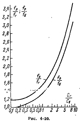
where V is the volume of air in the case, m3, equal to its internal volume minus the volume of the loudspeaker, which in the first approximation is 0,4 d4; d - diffuser diameter, m; 3) in relation to SG / CB using the nomogram in fig. 4-20 determine the ratio fP / fG provided by a case of a given volume V. The mechanical resonance frequency of the loudspeaker in the acoustic screen can be taken from Table. 4-11. If it is necessary to obtain an acoustic system with an existing loudspeaker in the form of a closed case with a resonant frequency fР, then the required volume of the case is determined in the following order: 1) take the value of the resonant frequency of the loudspeaker fG in the acoustic screen from the table. 4-11; 2) determine the flexibility of the suspensions of the mobile loudspeaker system SG; 3) having given the desired ratio fР / fГ, it is determined according to the graph in fig. 4-20 the corresponding ratio SG/CB and find the required flexibility of the volume of air SD in a closed case;
4) calculate the required volume of air inside the case in cubic meters using the formula The total internal volume of the case is obtained by adding the loudspeaker volume to the calculated value V. If the value of fG is unknown or it is difficult to determine it in an acoustic screen of a sufficiently large size, then it is possible to measure the frequency of the mechanical resonance of the loudspeaker fB without a screen and use the fP / fB curve in Fig. 4-20. The above calculation is valid only for frequencies f<;40/L ( L is the depth of the case in meters). In this regard, the rear side of the loudspeaker cone in a closed case must be protected from sound waves reflected by the inner walls, corresponding to higher frequencies, by covering these walls with sound-absorbing material. The dimensions of the closed case can be reduced by filling it with glass wool or similar material. Such filling is equivalent to increasing the volume of the case by 40%.
If the frequency /p obtained by calculation is low enough, then the loudspeaker should have Q about 1. If the frequency fP is unacceptably high, then good results are obtained by reducing the quality factor to a Q value of about 0,1; in this case, of course, it is necessary to raise the lower frequencies in the amplifier by about 6 dB / octave starting from the frequency
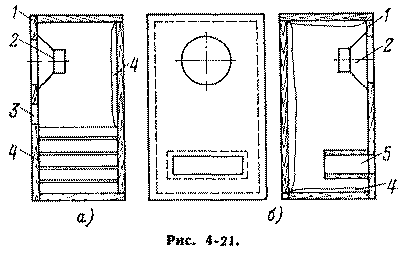
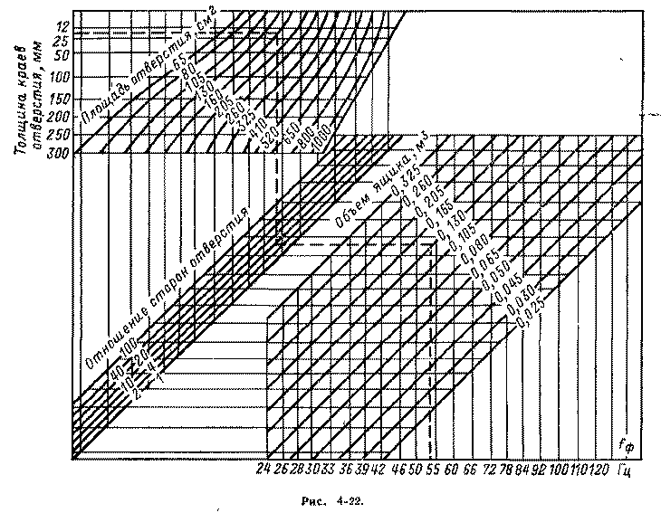
Phase inverter calculation The phase inverter is a case 1 (Fig. 4-21) with an additional hole 3 located next to the loudspeaker 2 mounted on the same wall and having an area, as a rule, equal to the area of the diffuser. Having given the depth of the phase-inverted hole, the ratio of its sides, having calculated the effective area of the diffuser (which determines the area of the hole) and taking the resonant frequency of the phase inverter fФ = fГ, according to the nomogram in Fig. 4-22 you can determine the required volume of the case.
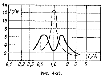
The distance from the end of the tunnel to the rear wall of the box must not be less than dG /2. At a frequency fФ, the phase inverter can be considered as an acoustic transformer that improves the matching of the loudspeaker with the air load. Although the acoustic power delivered by the front of the cone decreases at this frequency, the overall acoustic power can increase significantly. At the same time, non-linear distortions are significantly reduced and the nominal power of the loudspeaker is increased due to a decrease in the displacement amplitude of the diffuser. The depth of the phase-inverted hole can vary from the thickness of the case wall (Fig. 4-21, a) to a value approximately equal to 30 / fF when using tunnel 5 (Fig. 4-21, b). The considerable length of the tunnel allows the use of a small box. At frequencies below fF, the flexibility response of the air volume increases and forms a rigid connection between the air mass in the hole and the mass of the loudspeaker moving system. The mass of air, thus, is added to the mass of the moving system and, together with the flexibility of the suspensions, forms a mechanical circuit with a resonant frequency f1 < fФ . When the diffuser moves forward at this frequency, the air in the hole moves backward (and vice versa) and the radiation efficiency is negligible. At frequencies above fF, the resistance of the air mass in the hole becomes high and the phase inverter can be considered as a completely closed case. The rigidity of the air volume is added to the rigidity of the suspensions and, together with the mass of the moving system, forms a circuit with a resonant frequency f2 > fФ. The radiation from the phase-inverted hole at the frequency f2 is very small. The total electrical impedance of the loudspeaker RG in a phase inverter usually has two maxima (solid curve in Fig. 4-23) at frequencies f1 and f2, located on both sides of the resonance frequency of the loudspeaker in a flat acoustic screen fГ (dashed line in Fig. 4-23, where R is the resistance of the loudspeaker coil to direct current).
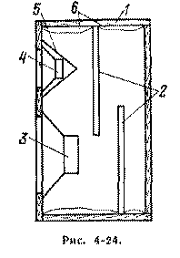
The peaks of the impedance of the loudspeaker in the phase inverter are significantly lower than the peak of the loudspeaker in the acoustic screen, however, the corresponding values of Q1 and Q2 are higher than Qr - loudspeaker in the acoustic screen. This disadvantage is especially pronounced at the frequency f1, since an increase in the speed of the diffuser leads to an increase in nonlinear distortions, the visibility of which is facilitated by the absence of useful radiation at this frequency. This phenomenon can be combated by limiting the output power of the amplifier at frequencies close to f1. If it is desirable that the frequency response of the loudspeaker in the phase inverter be horizontal in the lower part of the operating frequency range, starting from /r, then the condition Qr = 0,6 must be met. With an increase in QG, the value of Qg increases, and the value of QF decreases, and this causes uneven frequency response. If it is not possible to reduce Qr, then it is necessary to at least suppress the peak of the frequency response at the frequency f2, which occurs at QG > 0,6. This is achieved by introducing sound-absorbing material 4 into the box (see Fig. 4-21). Sometimes the entire volume is filled with glass wool. In this case, the area of the phase-inverted hole, obtained by calculation from the nomogram in Fig. 4-22 should be increased by 2,5 times. The introduction of a large amount of sound-absorbing material into the phase inverter leads to a weakening of the low-frequency radiation, and if you want to extend the characteristic towards these frequencies, at least up to fГ, you should ensure a significant increase in the low frequencies in the amplifier. The phase inverter is tuned by changing the area of the hole (for example, by a plate fixed so that its rotation changes the area of the hole) or the depth of the tunnel. It is necessary to strive to ensure that the frequency interval separating the resonant impedance peaks does not differ significantly from the octave; peak amplitudes were equal; any additional peaks caused by standing waves in the box were eliminated by adding damping material. The advantage of a phase inverter compared to a closed box of the same volume is an increase in acoustic power by approximately 5 dB in the range from one to two octaves and a decrease in non-linear distortion in the frequency range fФ - 2 / f at the same acoustic power. The disadvantage of a phase inverter is a faster decrease in acoustic power at frequencies below fФ than in a closed box, and the need for adjustment. Case construction In the case where the loudspeaker is mounted, resonance is possible at one or more frequencies of the sound range, leading to an unpleasant change in the timbre of sound reproduction. This phenomenon is most pronounced in partially or completely closed cases. The use of materials with a high density contributes to the reduction of wall vibrations. The plywood used for these purposes must be at least 20 mm thick. A good result is given by dry river sand, poured between two thin plywood sheets. The walls, especially the back and partly the front, must be reinforced with wooden blocks. It is possible to use chipboard. Case wall damping The inner surfaces of the case 1 (Fig. 4-24) are covered with a layer of sound-absorbing material 6 with a thickness of at least 10 mm (or one of the pairs of parallel surfaces with a layer of double thickness). However, standing waves at lower frequencies are not eliminated. The best result is obtained by dividing the volume of the case by one or more sound-absorbing partitions 2, for example, from felt 5-10 mm thick. Sections of the box that are separated from the loudspeaker by one or more partitions in this case require very little acoustic treatment. The tweeter 4 must be protected from radiation from the rear side of the woofer cone with several layers of sound-absorbing material, or a metal cap 5. The woofer 3 is placed at the bottom of the case.
Speaker placement The hole in which the loudspeaker is placed behaves like a pipe, the length of which is equal to the thickness of the wall or board. Resonances and anti-resonances of this tube, as well as reflections from the edges of the hole, cause uneven frequency response. Obvious recommendations are beveling the edges of the hole, or installing the loudspeaker in a thinner screen, which is then placed in a wall or normal thickness screen.
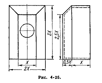
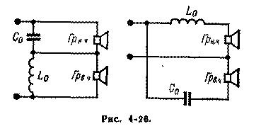
Drawer shape At lower frequencies, the loudspeaker radiates spherical waves, and the edges of the box, especially those that make up the front wall, form obstacles in the path of sound waves. This causes distortion of the wavefront (diffraction) and secondary radiation from the edges, which leads to interference phenomena, causing peaks and dips up to ± 5 dB in the frequency response. From the point of view of the fight against secondary radiation, the ideal shape is a sphere, the worst is a cube with a loudspeaker in the center of one of the sides. A rectangular cuboid with a loudspeaker placed closer to one of the short sides is preferable to a cube. However, the best approximation to the ideal is given by a rectangular truncated pyramid placed on a rectangular parallelepiped (Fig. 4-25). For any shape, it is desirable that the box has different values of linear dimensions; none of the linear dimensions was much larger or much smaller than the others; the largest box size should not exceed 1/4 wavelength of the lower frequency of the operating range. decorative fabric should not cause significant loss of acoustic power. The most suitable fabric is made of hard, strong (cotton or plastic) loosely woven threads. The use of fabrics made of soft and fluffy threads is undesirable. Grouping and Loudspeaker Phasing A group connection is formed by several identical loudspeakers placed close to each other in one acoustic screen. The loudspeaker group has a large radiation area at low frequencies (which would require a significant increase in the size and mass of the moving system when using one loudspeaker); however, the advantages of a separate loudspeaker with a relatively light moving system are retained in terms of transient and high frequency reproduction. The air resistance to radiation of each loudspeaker in the group increases at lower frequencies by a factor of n (ha is the number of loudspeakers in the group). This would make it possible to obtain a significant gain in acoustic power if the mass of the oscillating air did not simultaneously increase by the square root of n times. As a result, at n == 2 -:- 4, the acoustic power increases significantly, but still not by a factor of n (for the same electrical power), and a further increase in n gives almost no gain. An increase in the mass of the oscillating air lowers the resonance frequencies of each loudspeaker in the group and, consequently, expands the operating frequency range, especially significantly at large i. The most satisfactory connection of loudspeakers in a group is parallel; then Q of the system will not differ from QG. If it is necessary that the resistance of the group be equal to the resistance of one loudspeaker, then from the point of view of the best Q of the group, it is better to use a series-parallel connection of loudspeakers (the number of which should be equal to n2, where n = 1, 2, 3 ...). Whenever loudspeakers are connected in a group, they must be correctly phased: when a DC source (such as a low-voltage battery) is connected to the input terminals, the cones of all loudspeakers must be displaced in the same direction. Changing the direction of displacement of the loudspeaker diffuser is performed by changing the order of switching on its input ends. If placing a group of loudspeakers in a closed box is difficult - the required volume of the case, according to the calculation, turns out to be unacceptably large, then the loudspeakers can be placed in a small acoustic screen or a smaller box filled with absorbing material, compensating for the attenuation of radiation at low frequencies by appropriate correction in the amplifier. The disadvantages of group connection include a significant irregularity in the frequency response and directivity characteristics at higher frequencies. Two- and three-way speaker systems Speaker selection. Sound reproduction with class I quality can usually be obtained by using a full-range loudspeaker, such as 4GD4, 4GD7 or 4GD28, or by dividing the full frequency range corresponding to this class into two bands. To ensure sound reproduction with a quality of the "highest" class, it is necessary to divide the full range into three bands. The nominal frequency range of a loudspeaker intended to reproduce a particular band should be two octaves wider than this band when using filters with a slope of 6 dB / octave and one octave when using filters with a slope of 12 dB / octave. The crossover frequency of a two-way system is usually chosen from 400 to 1 Hz. In a three-way system, the low-frequency link can operate up to 200-300 Hz, the mid-frequency link up to 600-2 Hz. Near the crossover frequency, significant distortion often occurs due to the interaction of the loudspeakers. If the distances from each of the loudspeakers to the listener are unequal, then the frequency response of the system may have significant unevenness, determined by the phase relationships of the incoming signals. Separating filters. The simplest way to connect a tweeter is through a capacitor that protects the tweeter from overload at low frequencies. This inclusion is used when the main speaker does not have a sufficiently wide frequency range. Capacitor capacitance is calculated by the formula
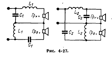
where fР is the crossover frequency, Hz; RP - loudspeaker impedance at frequency fР, Ohm. With a properly constructed filter, each loudspeaker should operate only in the frequency range for which it is designed. The filter loss in the passband should be as low as possible. The inductance and capacitance of the filter at different cutoff slopes, which is defined as the change in attenuation with a change in frequency per octave, are calculated using the following formulas.
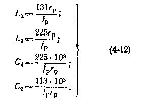
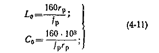
For a 6 dB/octave slope (filter by diagram in fig. 4-26) For a 12dB/octave slope (filter as shown in Figure 4-27)
In formulas (4-11) and (4-12), inductances have the dimension of millihenries and capacitances - microfarads.
Based on the calculation, capacitors with the nearest large nominal standard capacitances are selected. To select the capacitance, it is possible to connect several capacitors in parallel. Obviously, if the capacitance of the capacitor deviates from the value obtained by calculation, the separation frequency will differ from the specified one.
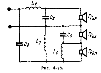
If the filter needs capacitances of the order of tens of microfarads and higher, then in order to reduce its dimensions, it is advisable to use electrolytic capacitors. Since the latter are polar, and will work in an alternating current circuit, then in each filter section it will be necessary to use two back-to-back capacitors, each of which should have a capacity as close as possible to that obtained by calculation. In the sections of the crossover filter of a transformerless transistor amplifier, one electrolytic capacitor can be used, observing the correct polarity of their inclusion. The filter for the three-way acoustic unit (Figure 4-28) is a combination of the two filters discussed above. The first separates the low-frequency region from the mid-frequency region; the latter is then divided by the second filter. Both filters do not have to have the same cutoff slope; they should only be calculated for one resistance.
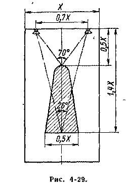
The method for calculating crossover filters is based on the assumption of equality and the active nature of the loudspeakers in the separated bands. Since the loudspeaker impedance at the crossover frequency can have a significant inductive component, in order to avoid frequency distortion in the overlap region, the inductance of the mid- and low-frequency loudspeakers should be taken into account when calculating as part of the filter, i.e., make a filter coil connected in series with the loudspeaker with an inductance less than calculated on the inductance of the loudspeaker. If the impedances of the loudspeakers in the links of the multiband system are not equal, then you should try to find equal impedances of the links by group connection (serial connection of high-frequency loudspeakers is acceptable). Parallel connection of two or three tweeters makes it possible to use them in combination with almost any subwoofer. A possible discrepancy in the values of the impedances of the acoustic system links can be eliminated by increasing the input impedance of the high-frequency link using a voltage divider made of resistors. If several tweeters are used in a two- or three-link system (for example, 1GD-3), then they should be placed in a case so that the angle between their axes in the horizontal plane is about 20-30 °. If in a multi-band sound reproducing system only one tweeter is used, which has an impedance greater than that of the woofer, then in order to equalize the load resistance of the crossover filter in the treble region, the tweeter should be shunted with a resistor of the appropriate resistance. Stereo speaker systems The loudspeakers of a two-channel stereo system must be strictly identical. They should be placed as shown in Fig. 4-29 where the "optimum" stereo effect area is shaded.
The orientation of loudspeakers depends on their directivity characteristics and must be determined experimentally. Loudspeaker axes should not intersect in the listening area. Publication: N. Bolshakov, rf.atnn.ru
Artificial leather for touch emulation
15.04.2024 Petgugu Global cat litter
15.04.2024 The attractiveness of caring men
14.04.2024
▪ CRT monitors will disappear faster than expected ▪ Traffic light for colorblind people ▪ The first 60 satellites of the global Internet
▪ site section Power Amplifiers. Article selection ▪ article A flatterer will always find a corner in the heart. Popular expression ▪ article Are there seas on the moon? Detailed answer ▪ Verbena officinalis article. Legends, cultivation, methods of application
Comments on the article: Anatoly A very useful article for real speaker design. Evgeny Instructive and helpful article. Much is clear. Thanks to the author! Dmitriy When I was little, it was already a very old book. Thanks anyway, smiled. Igor Fine! Keep it up! a guest The classic never gets old. Thanks for the collection.
Home page | Library | Articles | Website map | Site Reviews www.diagram.com.ua |


 Arabic
 Bengali
 Chinese
 English
 French
 German
 Hebrew
 Hindi
Hindi Italian
 Japanese
 Korean
 Malay
Malay Polish
 Portuguese
 Spanish
 Turkish
 Ukrainian
 Vietnamese





 Leave your comment on this article: