|
|


 Arabic
 Bengali
 Chinese
 English
 French
 German
 Hebrew
 Hindi
Hindi Italian
 Japanese
 Korean
 Malay
Malay Polish
 Portuguese
 Spanish
 Turkish
 Ukrainian
 Vietnamese
|
ENCYCLOPEDIA OF RADIO ELECTRONICS AND ELECTRICAL ENGINEERING On the principles of operation of noise suppressors. Encyclopedia of radio electronics and electrical engineering
Encyclopedia of radio electronics and electrical engineering / Audio equipment The issues of noise reduction in magnetic recording devices still attract the attention of radio amateurs and users of audio equipment. This is facilitated by the widespread use of imported tape recorders equipped with various noise reduction systems. The lack of information is partly due to the fact that the operating instructions of the equipment do not contain information about the features of the implementation and use of embedded systems. As a result, all sorts of speculations are circulating, but audio quality problems remain. First, it is worth noting that the word "noise suppressor" refers to two fundamentally different types of systems: one of them is designed to remove the noise already present in the phonogram (in English Denoiser), and the other - to prevent the accumulation of noise during transmission or recording of signals (Noise Reductor) . This ambiguity often gives rise to confusion and misunderstandings, therefore, to designate systems of the first type in a professional environment, it is customary to use the English word - "donozer" to distinguish them from systems of the second type. Well-known denoisers are dynamic filters (DNL, DNR, HUSH, "Mayak"), the principle of which is based on the simultaneous reduction of gain and signal and noise in a separate part of the spectrum (usually HF), where the useful signal can be neglected. Their advantage is their suitability for working with any signal source, and a serious drawback is the inevitable loss of some information. Now denoisers are mainly used to "clean up" old (or technically unsuccessful) records. They are rarely used in household equipment, usually only as an aid: after all, to obtain the optimal result, manual or automatic adjustment to a specific phonogram is required. The professional denoiser can be made as a stand-alone device (analogue or digital) or as a program for a computer. Let's take the NoNoise software package from Sonic Solutions as an example. You can get an idea of his work by listening to "The Beatles Live at the BBC" discs. The highest quality analog denoiser known to the author was made by Orban. This five-band dynamic filter has a unique ability to analyze both level and signal type, preventing reverb sounds and low-pitched high-frequency percussion from being eaten away. Systems of the second type (Dolby, dbx, High-Corn, Super-D, etc.) process the signal twice: the first time before recording or transmission, and the second time during reception or playback. Therefore, they are also called complementary, in contrast to the systems of the first type, which received the conditional name of non-complementary. Since the work of complementary systems is based on the use of a combination of a compressor and a dynamic range expander, they are often called companders or simply companders (COMpressor + exPANDER). Companders generally provide more noise reduction and less distortion in the music signal than denoisers. However, they impose certain requirements on the channel of reception-transmission (or recording-playback) and, as a result, are more "capricious" in application. The main, but not disputable, idea on which all noise reduction systems (UWBs) are based, and not just compander ones. is the assumption that. that noise impairs the perception of only weak signals, and with a strong signal (high volume) it is not audible due to the effect of masking a weak sound by a stronger one. Following this logic, there is no need for the noise level to be constant both in the absence and in the presence of a useful signal. That is, an increase in the absolute noise level with increasing signal level is considered acceptable and imperceptible by ear. This assumption opens the way to the construction of compander systems, in which the gains of both halves (compressor and expander) change depending on the signal level. In practice, this means that weak signals are amplified before they are fed into the transmission channel (for example, to a tape recorder), while a strong signal passes without changes (or even attenuates). This operation is called compression (compression) of the dynamic range. At the other end of the channel, an inverse conversion is performed, as a result of which the signal is brought to the original level range, and noise is reduced with a weak signal. Obviously, when implementing such a system, the dynamic range, measured as the ratio of the maximum transmitted signal to noise in the absence of a signal, can significantly exceed the same ratio measured for the transmission channel itself. It is clear that it is the first digit (as large) that appears as the value of the dynamic range in the UWB characteristics. However, it characterizes, rather, the range of acceptable levels of the input signal, while the signal-to-noise ratio in the presence of a signal (ie, the instantaneous signal-to-noise ratio) is determined primarily by the characteristics of the transmission channel itself. Without additional measures, such as special frequency equalization, the use of multiband systems, or a dynamic frequency response equalizer, the signal-to-noise ratio in the presence of a signal cannot exceed that of an unsquelched channel. Simply put, if the noise in the channel is heard even at the maximum signal level, there is no gain from using companding. As unfortunate as it may seem, this is exactly what happens in most cases. It is connected with the fact that the widespread assumption that any loud sound makes inaudible (masks) any weak sounds, including noise, is generally not true. Experts in psychoacoustics (the science of human perception of sounds) established the fact many decades ago that the masking phenomenon operates only in a limited frequency range, mainly near the frequency of a loud (masking) signal. This is most clearly reflected by the so-called "masking curves" (Fig. 1, 2), from which, in particular, it follows that in the presence of narrow-band sounds with a loudness of up to 90 ... 95 phon2, human hearing at a number of frequencies is still able to distinguish sounds , which are near the threshold of hearing in the absence of a masking signal. And only an increase in volume above about 95 phon leads to a reflex decrease in sensitivity, protecting the ear from damage.
Thus, the human ear has a kind of dynamic range compressor that allows it to work with signals in the dynamic range of about 130 dB, with a simultaneously perceived (instantaneous) dynamic range of about 90 dB. Therefore, if in the presence of a signal, noise and distortion do not exceed the absolute threshold of audibility or - 90 dB relative to the maximum signal level (taking into account uneven hearing sensitivity), then neither noise nor distortion will be heard under any conditions (and signals). However, these conditions are not provided even by most amplifiers, not to mention tape recorders. Therefore, another approach is more realistic: it is necessary to take measures to ensure that when playing various signals, the spectra of noise and distortion products of the sound transmission system would go as far as possible below the masking curves of these signals. In particular, for intermodulation distortion products, this means that the formation of difference tones during processing of high-frequency signals, as well as sum tones from low-frequency signals, is highly undesirable. At the same time, harmonic distortion of fundamental tones may well be -50 dB and go unnoticed. As for noises, the nature of their perception is different from that of "organized" sounds. The ability of human hearing to perceive noise depends on the spectrum and the rate of change of the useful signal, and the permissible signal-to-noise ratio in the presence of a signal with a level of 85 ... 95 dB (relative to the hearing threshold) is from 40 ... signal, up to about 45...75 dB for pure tones, especially at the edges of the audio frequency band. On average, it is 85 ... 50 dB. Based on this, we can say that in magnetic recording compander noise suppressors in most cases work "on the verge of a foul". Even if the compressor and expander are perfectly matched, if the record-playback channel has a signal-to-noise ratio in the presence of a maximum signal of less than 80 dB, there may be situations when noise will still be heard. The relative noise level in the recording-playback channels of analog tape recorders, even in the absence of a signal, as a rule, does not reach -80 dB. Appearing in the descriptions of some household tape recorders (for example, Tandberg SE-20), this value was achieved through the use of non-standard frequency correction, but with a loss of overload capacity at higher frequencies. Moreover, in the presence of a signal, the noise level in an analog tape recorder always increases, amounting to a value from -35 to -60 dB at the nominal signal level. This increased noise is caused by the presence of a signal and is roughly proportional to the signal strength. That is why it is called modulation noise. When recording a pure tone with a nominal level, the modulation noise spectrum on a good-quality tape recorder consists of two components: relatively narrow sidebands caused by parasitic amplitude and frequency modulation of the recorded signal, and broadband noise exceeding the pause noise level by 10 ... 25 dB, depending on signal frequency and tape quality. The sidebands, unless their total level does not exceed -40...-46 dB, with their small width (less than 5...8% of the central frequency), are almost never audible, since they are under the corresponding masking curve (Fig. 3a and 3b).
The broadband component, when playing pure tones, is quite often heard (in the form of “dirty” sound) even on a studio master tape recorder, since its overall level is rarely below -50 dB relative to the signal level. Unfortunately, there are only two ways to reduce the level of the wideband modulation noise component: improving the quality of the tapes and increasing the width of the recording tracks (each doubling gives a gain of only 3 dB). Modulation noise causes a lot of trouble: every blow on the keys of the piano is accompanied by crackling, as if they were laid with paper, the bass pipes of the organ are very hissing, string instruments begin to resemble wind instruments, “sand is pouring” from the cymbals, etc. By the way, the main reason for audible differences when When using different types of magnetic tapes, it is precisely the difference in the amount of intermodulation distortion and in the level (as well as the frequency dependence) of the modulation noise. The only way to reduce the visibility of broadband noise growth in the presence of a signal - the so-called "breathing" (breathing) or "pumping" (pumping) - is to introduce frequency equalization into the recorded signal so that the inverse frequency equalization during playback attenuates the parts of the noise spectrum that are not masked by the wanted signal (Fig. 4).
This frequency correction can be done in several ways. The first and most obvious is the division of the signal spectrum into separate bands, each of which has its own compander. Due to this, the presence of a strong signal in one of the bands does not lead to the appearance of noise in the others. It has long been established that to ensure an acceptable quality of operation of such a system, four to seven bands are required, which greatly complicates the design of the noise suppressor and makes its operation critical to the accuracy of the frequency response of the recording-playback channel. Thus, four-band Dolby-A built according to this principle requires tuning the frequency response of the tape recorder with an error of no more than ± 0,3 ... 0,5 dB. The second, simpler method is to use a fixed frequency equalization network, chosen in such a way that for most signals a frequency response is provided that is close to optimal for suppressing wideband noise. The quality of the operation of such a system depends very much on the competent selection of correction characteristics. A similar approach is used in most broadband companders (High Com, ADRS, dbx, etc.). Unfortunately, the correction characteristics in the wideband companders known to the author are far from optimal. The third way is to use companders with adaptive frequency response, which automatically adapt to the spectrum of the input signal. This approach (in combination with a chain with a fixed frequency response) is implemented in the Dolby-S / SR system. The nature of the change in the frequency characteristics of the compressor is shown in fig. 5. A system with an adaptive frequency response, as a rule, perfectly processes single pure tones and monophonic instruments, but, alas, the possibilities of adaptation are limited on a real signal. So, in the Dolby-S / SR system, in the presence of wideband signals, the “stretching” of the mid frequencies during recording stops. During playback, this leads to "breakthroughs" of noise and distortion in the frequency range from about 500 ... 800 Hz to 2 ... 4 kHz ("unnatural middle").
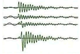
Of course, combinations of these methods are also possible. All the methods discussed above assume that the time and level characteristics of the compressor and expander are the same, and the recording-playback channel does not distort the structure of the signals. In practice, you can't count on this, so tracking errors inevitably occur in compander systems. Their influence on the final signal strongly depends on the structure of the system, but mainly comes down to two points: to the distortion of the processes of rise and fall of sounds, which changes their timbre, and to the appearance of operation noise (clicks and pops). The main reason for the appearance of clicks and pops is, for example, the following fact. When the compressor reacts quickly to a signal level jump (for example, when clapping your hands), all frequencies in the band processed by the compressor are attenuated simultaneously. Due to phase shifts, components of different frequencies arrive at the expander with a time delay, but are processed simultaneously. As a result, impulse errors appear in the output signal and, accordingly, actuation clicks (see Fig. 6a and 6b).
As for errors in signal level, most often they arise due to errors in the frequency response or the transmission coefficient of the recording-playback channel. Another cause of errors is the parasitic amplitude modulation of the signal in the recording-playback channel. And finally, at low signal levels, the penetration of various interferences into the control circuit of a compressor or expander is a problem. To reduce the penetration of radio-frequency (and infra-low-frequency) interference, the compander inputs must have band-pass filters that cut off signals with frequencies outside the audio frequency band. The absence of such a filter often leads to the inoperability of the noise suppressor in real conditions. It is precisely because of the circumstances listed above that the sound of a tape recorder equipped with any of the well-known companders will not be free from problems. Unfortunately, the perfect (or nearly flawless) compander denoiser does not exist today. Moreover, in connection with the development of digital technologies, the main attention of UWB developers is turned to the creation of denoisers. However, work to improve the companders is ongoing at the present time. Successful developments include, for example, a compander in the audio channel of a VHS-HiFi video recording system. Nevertheless, Dolby-B / C is still used in mass cassette recorders, less often Dolby-S or dbx. Therefore, each time, before pressing the button, it is worth considering whether it is necessary to use this compander for this recording? And if the original recording on a CD is of average quality, and a tape recorder. Author: S. Ageev, Moscow
Machine for thinning flowers in gardens
02.05.2024 Advanced Infrared Microscope
02.05.2024 Air trap for insects
01.05.2024
▪ The world's oceans accumulate mercury and release it into the atmosphere
▪ section of the site Children's scientific laboratory. Article selection ▪ article It is good where we are not. Popular expression ▪ article What is gum? Detailed answer ▪ article Canoe, like the Indians. Travel Tips ▪ article Imitation pearls. Simple recipes and tips ▪ article Penetrating ball. Focus Secret
Home page | Library | Articles | Website map | Site Reviews
www.diagram.com.ua |


 Leave your comment on this article: