|
|


 Arabic
 Bengali
 Chinese
 English
 French
 German
 Hebrew
 Hindi
Hindi Italian
 Japanese
 Korean
 Malay
Malay Polish
 Portuguese
 Spanish
 Turkish
 Ukrainian
 Vietnamese
|
ENCYCLOPEDIA OF RADIO ELECTRONICS AND ELECTRICAL ENGINEERING Features of the design of modern tube ultrasonic frequencies. Encyclopedia of radio electronics and electrical engineering
Encyclopedia of radio electronics and electrical engineering / Tube Power Amplifiers
Among the requirements that were once imposed on the low-frequency part of any radio engineering devices, the most important was efficiency. The amplifier was required to draw as little as possible from the power supply. A lot was sacrificed for this: for the final stage, for example, class A mode was regarded as uneconomical, and class AB2 was given preference over class AB1 wherever the given level of distortion allowed it. In second place were the requirements for the weight and dimensions of the main components of the ultrasonic frequency converter, in the first place, the output and transition transformers. Behind them were the requirements for maximum manufacturability, especially winding units, and ease of installation. The number of lamps and parts in the UZCH should ideally be minimal, and there was no question of using parts with a five percent tolerance. In the modern concept of high-quality sound reproduction, the quality of a modern tube amplifier stands out as its main advantage. Everything else, without regret, is brought to please this indicator. Concepts such as efficiency, weight, dimensions, cost, complexity of production are recognized not only as insignificant, but, in general, not worthy of attention. No technological difficulties are considered obstacles. The conveyor assembly process itself is questioned, and the repeatability of two devices that descended one after another from the conveyor is recognized as optional. The use of parts with a parametric tolerance of ± 5%, as before, is out of the question, but for a different reason: most resistors should have a deviation from the nominal value of no more than ± 1%. In the output transformer, the winding accuracy of the primary windings is limited to half or even a quarter (!) Turn, and the spread in their inductance values should be minimal. As for the size of the output transformers, the "bigger the better" approach is welcome. Of all the amplification classes according to the lamp mode, class A is preferred, even if we are talking about final stages with a power of 50 or 100 watts. The use of semiconductor devices in amplifiers is declared undesirable, while even in rectifiers kenotrons are preferred over silicon diodes. The latter, as an exception, are allowed to be used in rectifiers for lamp filament circuits. Each amplifier that is made is individually adjusted and tuned like a concert grand, with individual selection and tube selection taken for granted. With regard to the choice of types of lamps for the final stages, it is considered normal to dwell on such "prehistoric" direct-heated triodes as 2AZ, if their parameters meet the requirements of the designer. Even from what has already been said, it becomes clear that it simply does not make sense to talk about such concepts as the economy or cost of such ultrasonic frequencies. Indeed, an "average" UM3CH with an output power of 20 W can consume 120 ... 150 W from the network and cost 1500 ... .2000 dollars without an acoustic system. For radio amateurs who decide to try themselves in this area of design, a lot at first will seem, if not strange, then difficult to explain. In this regard, attention should be paid to the specific design features of modern tube ultrasonic frequencies. This article is devoted to the selection of radio tubes for modern amateur tube amplifiers, taking into account the possibilities of the domestic market of radio components. We divide the lamps into three groups: lamps for terminal and driver (pre-terminal) stages; tubes for pre-amp stages; lamps for rectifiers. In the first group, when working in class A, only triodes with a fairly linear anode-grid characteristic are used, as well as powerful beam tetrodes or (less often) pentodes, providing non-linear distortion of no more than 0,5% in an ultralinear switching circuit (also in class A) . It makes no sense to list all types of lamps used in the terminal stages by Western firms, since the possibility of acquiring them by domestic radio amateurs is extremely unlikely. Nevertheless, taking into account the increased opportunities for international trade, we indicate their American and European counterparts for domestic lamps. 2C3 (American analogue 2AZ) is a powerful two-volt direct-heated triode that provides a useful power of at least 20 watts in a push-pull transformer stage in class A. 6С4С - almost a complete analogue of the 2C3 lamp, but with a six-volt direct glow. 6С6С (American analogue of 6B4-G [1]) is an analogue of the 2AZ lamp, but with an indirect six-volt glow. These three types of triodes are today used in the final stages by almost all foreign companies that produce tube ultrasonic frequencies. Given the possible difficulties in acquiring these particular tubes, some domestic triodes - 6S19P [2] and 6S56P [3] can be recommended for radio amateurs. These lamps are mainly intended for electronic voltage stabilizers, but they are quite suitable for ultrasonic end stages. At the same time, this group of triodes has an important advantage: they operate at a lower anode voltage. As a result, in the power supply rectifier, you can do without scarce and large-sized oxide (electrolytic) capacitors for an operating voltage of 300-350 V. If you need more output power, the UMZCH is quite acceptable in each arm of the push-pull cascade (also called "pushpool" or PP in the English abbreviation) use two lamps connected in parallel.
The domestic 6H13S lamp (a complete analogue of the American 6AS7-GT) can also be attributed to the same group of terminal triodes, each of its two triodes allows dissipation power at the anode up to 13 watts. It operates at low anode voltage (90 V). If both triodes of one cylinder are connected in parallel, then, using two such lamps in the final stage, it is possible to obtain a useful output power of at least 20 watts. The choice of powerful beam tetrodes and terminal pentodes for the output push-pull stage according to the ultralinear switching circuit seems to be more modest (in the usual switching circuit, they are hardly suitable for modern UMZCH). Here, German lamps EL-34 and EL-12 can be considered the best [1]. The complete domestic analogue of the first of them (if not talking about quality) is the 6P27S lamp, there is no analogue of the second among domestic and American lamps. Finally, it is permissible to use a 6P41S lamp specially designed for frame scanning schemes for color TVs. As for the output lamps for horizontal scanning of TVs, due to their specific features for the final stages of the UMZCH, they are of little use due to the extremely low efficiency in class A. If a radio amateur is satisfied with an undistorted output power of 10 W (usually sufficient for a residential apartment), it is best to use the most common terminal pentode of the EL-84 type in its time in world and domestic practice, the analogue of which was the domestic lamp 6P14P (6P14P-V). The situation is much simpler with a group of lamps for phase-inverted, pre-terminal cascades and pre-amplification cascades. The vast majority of Western manufacturers of modern tube ultrasonic frequencies limit their range to four types. Two of them are representatives of more "ancient" series. These are American eight-pin ("octal") double triodes of types 6SN7-GT and 6SL7-GT, analogues of which were very widespread domestic lamps 6H8C and 6H9C at one time. The other two are Western European double triodes of the finger-type ECC-87 and ECC-83 series, to which domestic lamps 6N1P and 6N2P are very close. In addition, specifically for the input (first) stages of pre-amplification, it is possible to recommend high-frequency single triodes of the 6S3P and 6S4P types, which were not previously used for this purpose, and are designed to amplify and generate microwave signals. Such triodes are characterized by a very low level of intrinsic noise (the equivalent resistance of internal noise is no more than 170 ohms) and negligible leakage currents in the filament-cathode circuit. This circumstance is extremely important to achieve the overall level of self-hum and ultrasonic noise up to about -70 ... -80 dB. More details about the cause of the background in the first stage of the amplifier will be discussed in the part devoted to the design of specific ultrasonic frequencies. And finally, the third group - lamps for rectifiers. At first glance, it may seem absurd to use kenotrons today, when there is a large range of semiconductor diodes and diode assemblies that not only completely replace kenotrons, but also have incomparably better performance in terms of efficiency. Nevertheless, no Western company uses semiconductor devices in power supplies, preferring lamps. A smooth increase in the current of the kenotron after switching on makes it possible in a simple way to prevent the appearance of high voltage on the anodes of lamps (first of all, powerful ones) until their cathodes warm up to a temperature that ensures the appearance of a rather dense "electron cloud". Neglect of this condition very soon leads to the so-called "poisoning" of the cathodes of high-power lamps, their premature aging and failure. The range of used kenotrons is relatively small and includes the following types: 5TsZS, 5Ts8S, 5Ts9S. From American lamps, 5U4G, 5Y3G, 5V4G are more commonly used, and from Western European lamps - EZ-12 [3]. To finish only a slightly touched topic about lamps, we add that for lamps of all cascades (and especially terminal lamps), only ceramic, not plastic, panels should be used. As for the lamps of the preliminary stages of amplification, their panels must have a protruding flange, on which a metal cylindrical screen is put on from the outside, protecting the lamp from external pickups. For the input stage lamp, it is desirable to use a screen that also protects against magnetic interference (it can be made independently from galvanized sheet steel). Unlike a transistor amplifier, in a tube design, there is usually a need for an output transformer to match the low resistance load with the relatively high internal resistance of the tube. The output transformer also separates the useful AC component of the signal from the unnecessary DC component. The practice of creating a large number of tube ultrasonic frequencies and analyzing their work showed that it is transformers that are the main source of nonlinear and frequency distortions and, in essence, limit both the amplifier bandwidth and the minimum achievable THD value. And a lot depends on their design. Many modern ultrasonic frequencies are performed with push-pull end stages and operate in a very wide frequency range - 20 Hz ... 20 kHz. The cut-off frequency ratio is 1:1000, which creates fundamentally different, and sometimes contradictory, mutually exclusive operating conditions for the transformer and, consequently, the requirements for it. What is the essence of these contradictions? For a certain average frequency of the operating range (say, 1 kHz), the inductive reactance of the primary winding of the transformer is much higher than its active resistance, which is determined solely by the length and diameter of the winding wire. For example, for a typical industrial tube radio transformer, the inductance of the primary winding is in the range of 10 ... 15 H, and the active resistance is approximately 500 ... 800 Ohms. At a frequency of 1 kHz, the inductive reactance of such a winding (XL) is 62 kOhm, so the active resistance of the winding connected in series with its inductive reactance can simply be neglected - the losses on it are about 1%. However, at the extreme lower frequency of the operating range (and even in the best and most expensive models of tube radios it turned out to be within 60 ... useful signal. If today we want to use such a transformer in a modern amplifier, where the lower limit of the operating range is at least 20 Hz, then at this frequency the signal loss will already reach 70%, i.e., a signal with a frequency of 20 Hz cannot be reproduced at all. So what should be done to solve this problem? The answer is obvious: it is necessary to increase the inductance of the primary winding and reduce its active resistance. An increase in inductance can be achieved by increasing the number of turns of the winding and reducing losses in the magnetic circuit of the transformer. But with an increase in the number of turns, the active resistance of the winding also increases. There is only one way to reduce the winding resistance with an increase in the number of its turns - an increase in the cross section (diameter) of the winding wire, but more space will be required to place the winding on the frame, which will entail an increase in the dimensions of the transformer. What real values of the inductance of the primary winding and its active resistance (r) can be considered acceptable for a modern UMZCH with a lower bandwidth limit of 20 Hz? If we set the maximum allowable signal loss value at the lower frequency of the range to 10%, then the calculations give the value of the inductance L - 40 H. Reactive and active resistance: Xl \u2d 6,28πfL \u20d 40-5-XNUMX \uXNUMXd XNUMX kOhm; r = 0,5 kOhm (assuming r = 0,1 Xl). The constructive calculation of such a transformer (for a push-pull cascade, the primary winding consists of two sections) gives values in the range of 1500-2500 turns of PEL or PEV wire 0,44-0,51 mm for the primary winding and 50-150 turns of wire with a diameter of 0,8-1,2 .20 mm - for the secondary. In order for these windings to be placed on the frame, the dimensions of its "window" must be about 50x10 mm, which leads to the need to use a transformer with a magnetic circuit cross section of at least 2 cm10 for an amplifier with an output power of 15 ... 40 W. For amplifiers with an output power of 15 W, the cross section accordingly increases to 18 ... 2 cmXNUMX. In order for a radio amateur to connect these numbers with real ideas about transformers, we recall that such a package of iron (section 30x63 mm) had a power transformer for the Rubin-102 TV with a power of 150 W! This is the price today for the real lower end of the amplifier bandwidth of 20 Hz. Now let's talk about the price difference in the parameters of the two halves of the primary winding of the output transformer of the push-pull UMZCH, wound in the traditional way, invariably used in industrial production. First, one half of the primary winding was wound on the frame, then one or more layers of insulation followed, and after it the second half of the winding was wound. In this case, the length of the first turn (at the base of the frame) was significantly less than the length of the last turn of the second half of the winding, and their resistance turns out to be different. To this it should be added that the inductances of both halves of the winding will not be the same, since the formula for the inductance of a multilayer cylindrical coil includes the diameters of the lower and upper turns, and they will turn out to be different for the two halves of the winding. Without loading the reader with cumbersome calculations, we note that with a total resistance of 500 ohms, the lower half of the winding has a resistance of 200, and the upper half has a resistance of 300 ohms. Approximately the same difference is obtained for other parasitic parameters of these halves (leakage inductance, interturn capacitance of the windings). Even an approximate calculation leads us to an interesting result. If two triodes with an anode current of 100 mA each are used in the final stage at a source voltage of 120 V (for example, 6S19P lamps), then as a result of the voltage drop across the constant active resistance of the windings, the difference in voltage at the anodes of the two lamps is about 10%. At low frequencies, when the inductive resistance of the windings begins to shunt the load, the difference in the inductance of the halves of the winding leads to asymmetry and an increase in the nonlinearity of the powerful cascade. Similar symmetry breaking also occurs in the region of high sound frequencies. Thus, with the "classical" winding technology of the transformer and the equality of the number of turns of the two halves of the primary winding, the resistance and inductance will differ, which, of course, excludes the possibility of obtaining nonlinear distortions of less than 1%. As a result, the conclusion follows: the requirements for the design of transformers are by no means excessive, and in the manufacture of transformers, instructions and recommendations must be followed exactly.
The winding of each of the two coils in this case does not require any special technological methods and is carried out on a conventional winding machine with a stacker, which makes it possible to obtain a dense ordinary layer-by-layer winding "coil to coil". It is completely unacceptable to wind coils "in bulk". Over the half of the primary winding on each of the two coils, half the turns of the secondary winding are wound in the same way, and after assembling the transformer, both halves of both the primary and secondary windings are connected in series. Such a transformer is distinguished by the symmetry of the parts of its windings and has insignificant external stray fields. It should be noted that the ends of the sections of the primary winding should be connected to a power source, and the beginning - to the anodes of the lamps. Parasitic connections in the transformer are minimal. However, it is quite possible to make a good output transformer on an armored magnetic core assembled from separate W-shaped plates, however, its manufacture will be more laborious and will require additional operations. The first difficulty on this path is connected with the magnetic circuit itself. For audio frequency transformers, plates with a thickness of not more than 0,35 mm are suitable. Having assembled a package of the required thickness, you should add at least 10% of additional "reserve" plates (and jumpers too) to it in reserve. All plates and jumpers, checked for the absence of burrs and notches, must be coated on both sides with a thin layer of nitro-paint or liquid zapon-lacquer from a spray gun, and then dried thoroughly. For a transformer with an armored magnetic circuit, a sectioned frame is required. Most likely, none of the finished industrial products will work, especially if it is non-separable. But before proceeding with the independent manufacture of the frame, you need to stop at one of the three winding options shown in Fig. 1.
Option "a" assumes a frame, divided exactly in half by an additional inner cheek for the entire height of the window. In this case, one half of the primary winding is wound in each section, on top of which, after several layers of insulation (cable paper or varnished cloth), exactly half of the turns of the secondary winding are laid in each section. Sections of the primary and secondary windings are connected in series. In option "b", the middle cheek is made of a smaller height - flush with the halves of the primary winding. After their winding, 2-3 layers of insulation (cable paper) are laid over the entire width of the frame and from above, also over the entire width of the frame, the entire secondary winding is wound without breaking. And finally, option "c" provides for the division of the frame into three sections. In the two extreme sections, halves of the primary winding are wound, and in the middle - the entire secondary winding. Electrically, all three options are equivalent, so the designer can choose any of them. To preserve the properties achieved in two-coil designs of transformers, the sections of the primary winding should be wound in different directions, then the ends of the sections, as in the two-coil version, can be connected to a power source, and the beginnings to the anodes of the lamps. The plates of the magnetic core are assembled end-to-end, without a gap, since there is no DC bias in push-pull circuits. It is desirable to subject a fully assembled transformer to moisture-proof treatment, even at home. In an iron can or any other similar container, inside which the entire or at least half of the output transformer can fit, you need to melt and warm up candle wax, paraffin, stearin or industrial ceresin well. The transformer is lowered into the melt and kept in it, heating for 2 ... 3 minutes. If only a part of the transformer fits in the bank, you should turn it over and “boil” it again for 2 ... 3 minutes. The impregnated transformer must be removed and allowed to drain excess wax. After cooling to room temperature, frozen drips, if they interfere with the fastening of the transformer, can be carefully removed with a wooden or plastic spatula (but not with a steel knife!). It is advisable to place the finished transformer in a metal casing-screen in order to exclude the effect of its electric and magnetic fields on lamps, an open printed circuit board, regulators and connecting wires; this will prevent uncontrolled parasitic feedbacks. Sectioning the winding is also useful in the manufacture of the output transformer of a single-ended amplifier (powerful or preliminary stage). When designing transformers, one should be guided by the following:
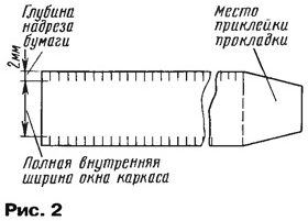
As an example, we give the design and electrical data of the output transformer for amplifiers using E1_-34 (6P27S) lamps in a push-pull terminal stage according to an ultralinear circuit. The same transformer can be used together with EL-84 (6P14P) lamps. However, it should be immediately warned that the exact repetition of the given data with an accuracy of one turn and the use of the recommended diameters of the winding wire may not always be justified, and in some cases lead to the fact that all the windings will not fit in the frame window. The reason is simple: the packages of magnetic circuits used by different radio amateurs can sometimes vary greatly in the quality of the transformer steel, which leads to different inductance values with exactly the same number of turns of the coils and, consequently, to a non-optimal mode of the terminal lamps in terms of undistorted power output. As for filling the window with windings, here the difference may turn out to be even greater, since it depends on the winding wires used (PETV-2, PEL, PEV-1, PEV-2, etc.), having at the same diameter for copper (for example, 0,2 mm) different outer diameter - 0,215 ... 0,235 mm. Deviation is also possible due to the number of layers and the thickness of the insulation between layers and windings - cigarette, capacitor, cable paper, varnished cloth, coated paper, drawing paper are applicable. Filling deteriorates with a decrease in the density of winding and the tension force of the wire, as well as the completeness of filling each layer of winding with turns. And now about the design of the output transformer for a power amplifier with 6P27S lamps. Magnetic circuit - W-shaped armored USh-32 (steel 1513, 1514, plate thickness 0,35 mm), package thickness - 40 mm, cross section - 12,8 cm2, window size (without taking into account the thickness of its walls) - 32x80 mm. Useful cross-section used for placing windings is not less than 21 cm2, working width of one winding layer is not less than 76 mm. The choice of frame design (see Fig. 1) and the winding method is determined by the radio amateur himself. Each half of the primary winding contains 1200 turns of PEL or PEV wire with a diameter of 0,44 mm. Branch for connecting the shielding mesh from the 500th turn. However, for amateur experimenters, we recommend making three taps: from the 500th, 600th and 700th turns in order to be able to select the optimal operating time of the final stage during the amplifier adjustment process - the maximum output power at a given level of nonlinearity (harmonic spectrum ). In this transformer, with dense row winding and the use of a frame with two sections (one partition in the middle), approximately 75 turns fit in one layer of the primary winding, and the entire winding will require 16 rows and, taking into account the thickness and number of insulation layers, will take slightly less than half the window section. In the remaining part of the window, a secondary winding is placed (one half in each section). The primary and secondary windings are separated by 2-3 layers of thick cable paper, which can be completely replaced with strips of drawing paper or coated paper. Paper strips for interlayer insulation must be cut 4 mm wider than the internal size of the frame window, and on both sides of the tape, make cuts with a depth of 2 ... 3 mm every 3 ... 5 mm, as shown in fig. 2. When winding such a tape, its edges are bent, which completely and reliably prevents the extreme turns from falling into the underlying layers, allowing the full width of the window to be used for winding.
The secondary winding contains 120 turns of PEV or PEL wire with a diameter of 1 mm and is divided into 8 parts (sections). In each half of the window, 4 sections of 15 turns are wound (60 turns in total). Thus, in total, many leads can come out of the coil. In order not to get tangled up in them, before winding in the cheeks of the frame in certain places, you need to drill holes for the wire leads. Each of them should be numbered, and during the winding process, mark on a sheet of paper the correspondence of the leads and taps of the windings to the numbers of the holes on the frame. After winding the entire transformer, you need to draw a transformer diagram on a piece of paper measuring 30x70 mm and put down the numbers of the corresponding pins on it. This passport must be glued to the visible protruding part of the frame, protecting it from above with a strip of transparent adhesive tape of the appropriate width. This information may be useful later. The dynamic range of reproduction is one of the most important indicators of any high-quality audio path. The dynamic range of an amplifier is primarily determined by the noise floor of the amplifier itself. These noises are made up of three components:
To reduce the level of ripple in the power circuits to the required level, the capacitances of the oxide capacitors of the filters are increased, and a choke is introduced into the power filter. In addition, special units and components are used - an electronic voltage stabilizer at the output of the rectifier, chokes with a compensation winding or tuning the circuit to resonance at the ripple frequency. To reduce the influence of the second factor, lamps with a minimum passport value of their own noise are selected for the input stage. To power the filament, direct current should be used from a separate rectifier with an output voltage reduced to 6 V, a protective potential difference should be created between the cathode and the filament of the lamps of the preliminary stages. In connection with the last recommendation, we will consider a method for reducing the background with a frequency of 50 Hz that occurs in the heater-cathode circuit of the first lamp. An electron lamp always has leakage resistance Ryt between the filament and the cathode (Fig. 3a). Due to the positive voltage on the cathode relative to the common wire (chassis), corresponding to the automatic bias voltage of +2 V, the heater-cathode section can be considered as an open diode with an internal resistance equal to Ru, the value of which ranges from hundreds to thousands of kilo-ohms. Let's take this resistance equal to 470 kOhm (Fig. 3,6 shows the equivalent circuit of the filament-cathode circuit).
Naturally, a current will flow through this diode along the circuit of the filament winding - the heater-cathode gap - the automatic bias resistor and the voltage on the winding (6,3 V) will be divided by the resistances Rut and in a ratio of 1000: 1. A parasitic AC voltage of approximately 0,0063 V will appear on the auto-bias resistor. This voltage is amplified by all subsequent stages and creates a noticeable background voltage at the amplifier output. If we take into account that the sensitivity of the UHF is usually 100 ... .200 mV, then the nominal level of the useful signal is only twenty to thirty times greater than the spurious background. The conductivity of the parasitic heater-cathode diode can be eliminated by creating a positive potential on the filament, which exceeds in value the sum of the cathode voltage and the amplitude of the filament voltage. One of the options for such a shift is shown in Fig. 4.
The lamp heater circuit is not connected to the chassis here, and a positive voltage is supplied to this circuit from an additional voltage divider through a tuning resistor, with which, when adjusting the amplifier, a minimum hum level is achieved. A constant voltage of +25 ... 30 V can be taken from a common rectifier and removed from the lower arm of the divider, which consists of two fixed resistors and an additional filter capacitor. It should be recalled that the level of this background is very insignificant, therefore it should be measured with a tube millivoltmeter at a limit of no more than 5 mV, and even better with an oscilloscope, since the background with a frequency of 50 Hz clearly stands out among other interference and noise. Now about the third, most important factor that affects the level of the amplifier's own background. Proper installation of input circuits and circuits of functional adjustments (loudness, tone, balance) largely eliminates the influence of this factor on the overall noise level. In order to understand the principles of competent installation, consider Fig. 5, which shows the connection of the grid circuit of the lamp with an input connector some distance away from the lamp. The recommendations will be almost the same for connecting any two nodes of the audio path or ultrasonic frequency converter, one of which is the signal source and the other is the load.
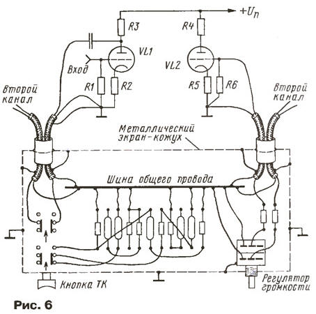
This can be a microphone and a microphone stage amplifier lamp, an input jack for a tape recorder and a switch for the type of work, or the first two UHF stages and a tone control unit. In the latter case, the signal source is the anode of the lamp of the first stage, and the load is the resistor in the grid circuit of the lamp of the second stage, and, therefore, no connections to the housing inside this section are allowed. In other words, inside the closed metal case of the tone control box, no part should be connected directly to the chassis or shielding, but only to a bus bar isolated from the case, as shown in fig. 6.
Now about the shielded wires themselves. None of the industrially produced types of wires in a "pure" form is suitable for a modern high-end tube amplifier. All shielded wires are best done by yourself - it's easy. On fig. 7 shows that wires of different diameters are placed inside the shielding braid. This difference corresponds to the real design. All shielded wires are made according to the principle of a matryoshka doll. Two wires of different diameters are placed inside an ordinary metal shielding braid: one is thinner (signal) necessarily colored stranded in PVC or fluoroplastic insulation with a cross section of 0,2 ... 0,35 mm2, the other is also stranded, but with a cross section of at least 0,5 mm2 - "cold".
Both of these wires, together with the shielding braid, should be placed in a polyvinyl chloride (PVC) tube. When making an amplifier for mounting various circuits, it is useful to use wires in insulation of different colors. The choice of colors themselves, of course, can be arbitrary depending on the capabilities of the radio amateur, but it is still better to follow some rules. So, all wires connected to a common wire are best made black and thick (section 0,5 ... 0,75 mm2). The wires of the power circuits (positive polarity) from the rectifier are red, and if there are several rectifiers, they are red, pink, orange. All signal wires of one of the stereo channels are green, and the other is blue or cyan. The filament circuits of the lamps are white or grey. For circuits of auxiliary devices and systems, brown, yellow and thin black or white can be distinguished. Such a separation will greatly simplify the installation check and eliminate confusion when wiring two-channel volume and tone controls (which one is from the left channel, which one is from the right). For self-manufacturing of shielded connecting cables, you must either take a separate metal braid or remove it from the shielded wire, then thread two insulated wires into the braid: one is a thin "signal" wire, the other is a thick zero wire, and all this, together with the braid, is pulled inside the tube from PVC of the appropriate diameter. In principle, this can be done in two different ways: to make each individual shielded wire of a predetermined length, or to immediately prepare 10 ... 15 m of cable, and then cut pieces of the desired length. The pins of the interconnect cable are desoldered to the appropriate connectors, of which the most commonly used are "tulip" (RCA), "jack", "mini-jack". When installing incandescent circuits and network wires in an amplifier, both wires (you can use the same color) are placed inside one braid and the braid is also insulated with a PVC tube. Now about the "zero" bus mentioned above inside the shielded blocks. If the block contains a printed circuit board with radio elements, then one of the printed tracks (as wide as possible) can play the role of a bus. It should be borne in mind that the input and output impedances of tube amplifier stages are usually an order of magnitude greater than those of transistor amplifiers, and are measured in hundreds of kilo-ohms, therefore, the intrinsic capacitances of shielded wires have a significant impact on the frequency response of ultrasonic frequencies in the HF region. You should not use modern thin and ultra-thin (diameter 3, 2 and even 1,5 mm) "proprietary" shielded wires. In any case, shielded connections should be kept as short as possible. In the previous parts of the article, issues related to ways to ensure high quality indicators of tube amplifiers were considered. However, these indicators may not be realized if the signal sources - tape recorder, player, microphone - are connected to the input of the amplifier incorrectly. Connecting external signal sources with different output impedance inevitably reduces the dynamic range of the entire system due to interference, and also limits the upper limit of the frequency range due to the shunting effect of the capacitance of the connecting cables. And although it is impossible to completely eliminate these harmful influences, it is quite possible to reduce them by properly connecting the signal source to the input of the amplifier. This question is quite serious, since we are talking about connecting cables subject to various external pickups, for example, from a 220 V electrical network passing nearby. In addition, we are talking about the transmission of signals of a very low level (about 5 ... 200 mV) and to also from sources with high internal resistance (up to hundreds of kilo-ohms). These two factors require the use of special measures to prevent interference from outside and to exclude the mutual influence of cables from several sources. The situation is aggravated by the fact that different solutions are optimal for different signal sources, so we will try to give recommendations for each individual case. Lines from a piezoelectric or electromagnetic pickup, as well as from a microphone, are most susceptible to interference. For these circuits, a general solution can be proposed using a thin coaxial cable with an outer diameter of 4 ... 5 mm and a capacitance of 70 ... 115 pF per meter, for example, RK-50-2-13, RK-50-3-13, RK -50-2-21 (their old names are RK-19, RK-55, RKTF-91, respectively) or RK-75-2-21. For a stereo device, two pieces of cable of the required length, placed in one common metal braid, form a cable with high noise immunity. It is also desirable to insulate the outer braid with a PVC tube. It is permissible to put the tube on a long cable in parts 0,5 ... 1 m long. Unsoldering interconnect cables should be done as shown in Fig. 7. For a microphone, if it is not stereo, there is no need for two separate cables, however, using the cable braid as a second wire is not desirable here. For a microphone line longer than 1 m, it is desirable to use a two-wire cable with a shielding braid, similar to the domestic cable of the KMM type. The connection of both wires and braid is clear from the figure. An interconnect cable for a stereo tuner, tape recorder and CD player can also be made in one screen. Three multi-colored wires must be pulled into one common shielding braid: two signal wires for the left and right channels (for example, green and blue) and one thicker one (black or white) for the common wire. All this cable, together with the braid, must be insulated with a PVC tube. The signal from the TV can be transported with a conventional coaxial cable or a shielded wire, using its braid as a neutral wire, since the level of the TV's own background often does not allow talking about high-quality sound reproduction. Here it should only be borne in mind that the sound signal can be removed if there is no corresponding connector, both from the output of the UMZCH TV and from the load of the frequency detector. The UMZCH output is usually low-impedance, and the connecting cable does not create additional losses in the high-frequency part of the spectrum. However, the output level will depend entirely on the TV's volume control, and if there is no phone jack, it will not be possible to reproduce sound only through an external amplifier. The signal at the output of the UMZCH TV, as a rule, is not of high quality. It is better to use the second method and take the signal directly from the output of the frequency detector. True, in this case, you will have to open the TV and connect this signal to an additional RCA connector, which can be installed on the carrier frame of the TV or on a removable back wall, and connect the connecting line to this connector. But in this case, the cable will also need to be shielded with two wires inside the braid. The connecting line from the radio broadcasting network, if one needs to be connected to an amplifier, differs from TVM in that both wires are equivalent inside the dwelling: ballast resistors are connected in series in the circuit of each of the two wires of the broadcasting network. The signal loss in this case can be completely neglected, since the signal in the line is much larger than from other signal sources. Literature
Author: G.Gendin, Moscow
Machine for thinning flowers in gardens
02.05.2024 Advanced Infrared Microscope
02.05.2024 Air trap for insects
01.05.2024
▪ The admixture of carbon improves the electrical conductivity of copper ▪ Panasonic and Sony - new AVCHD technology ▪ Augmented Reality Headset Glass Enterprise Edition 2 ▪ Lite-On releases cameras for a third of laptops
▪ section of the site Children's scientific laboratory. Article selection ▪ Khlestakov's article. Popular expression ▪ article What natural disaster restored hearing and sight to one American? Detailed answer ▪ Article Head of Sales. Job description
Home page | Library | Articles | Website map | Site Reviews
www.diagram.com.ua |

 The renewed interest of audiophiles and radio amateurs in tube amplifiers was promoted by a fundamentally new concept of designing tube ultrasonic frequencies, which differs significantly from the principles of building "old" amplifiers and is somewhat diametrically opposed to "old" ideas. What was previously put at the forefront in the creation of mass household sound-reproducing equipment is now generally swept aside as a third-rate one.
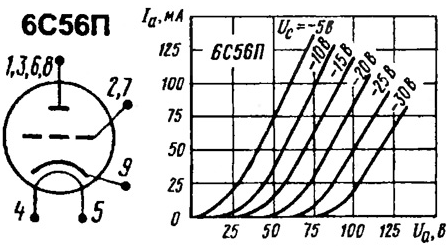
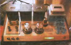
 Now let's move on to the practical side of things and start with the choice of the magnetic circuit for the output transformers. Taking into account the previously mentioned features of push-pull UMZCH transformers and for ease of winding, it is better to use strip split rod-type magnetic circuits (PL, see photo). On each of the two rods, two identical frames are placed with two identical windings (similar leads in one direction), with practically the same electrical parameters.


 Leave your comment on this article: